Projection optical system
A technology of projection optical system and optical part, applied in the field of projection optical system, can solve problems such as brightness limitation and spectral loss, and achieve the effect of reducing light loss and improving output brightness
- Summary
- Abstract
- Description
- Claims
- Application Information
AI Technical Summary
Problems solved by technology
Method used
Image

Examples
Embodiment 1
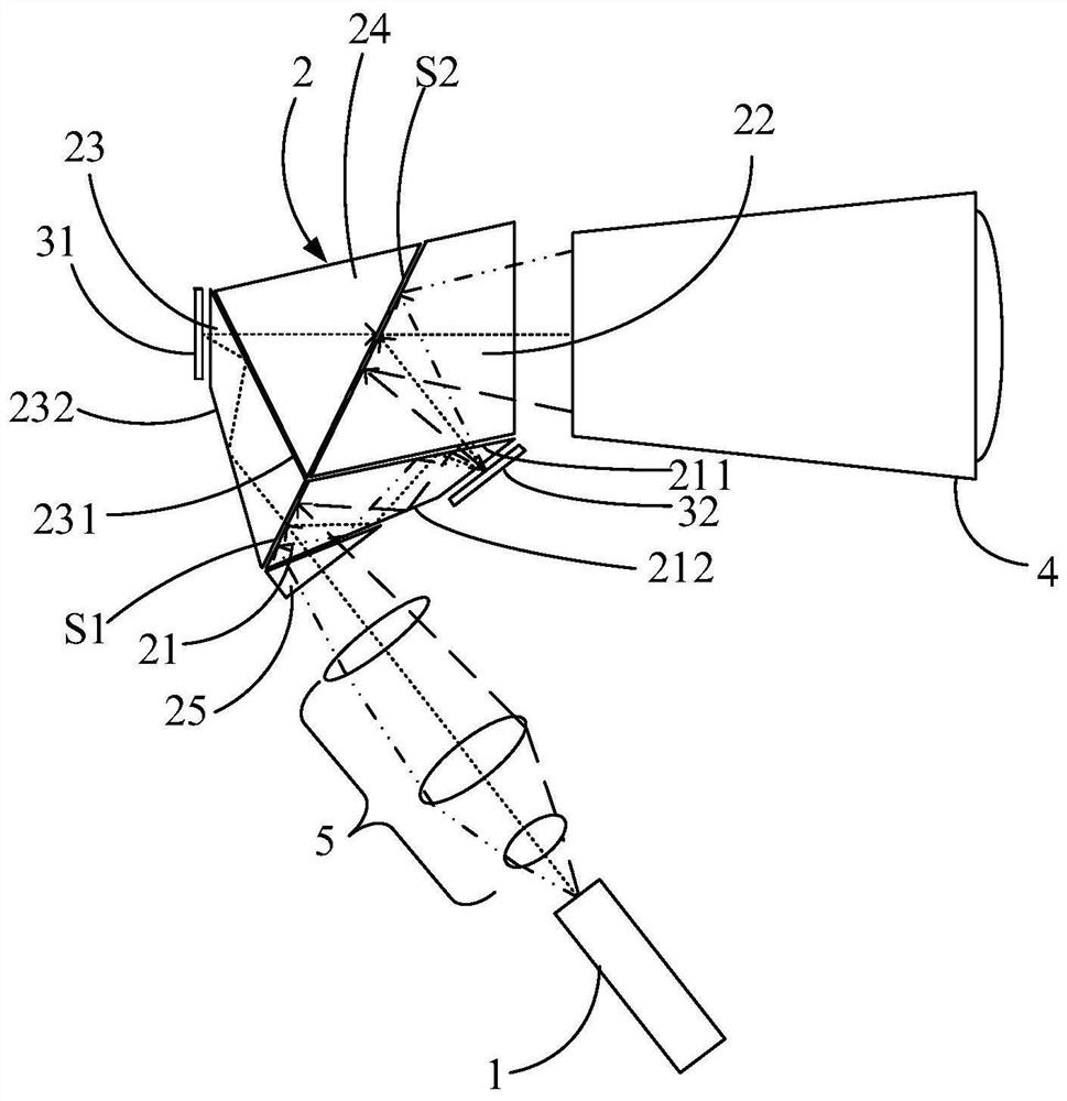
[0023] see figure 1 , figure 1 It is a schematic structural diagram of the first embodiment of the projection optical system of the present application. The projection optical system includes: a light source 1 , a light splitting and combining device 2 , a first spatial light modulator 31 and a second spatial light modulator 32 .
[0024] The light source 1 is used for emitting an illuminating light beam, and the illuminating light beam contains at least two primary color lights. Wherein, the light source 1 may include solid light sources such as laser diodes and light emitting diodes. The illumination beam includes a plurality of sub-beams. When the illumination beam is incident on the light splitting and combining device 2, there are multiple incident angles. In the embodiment of the present invention, a small beam of light with the same incident angle is used as a sub-beam.
[0025] The light splitting and combining device 2 is used for compensating the optical path diff...
Embodiment 2
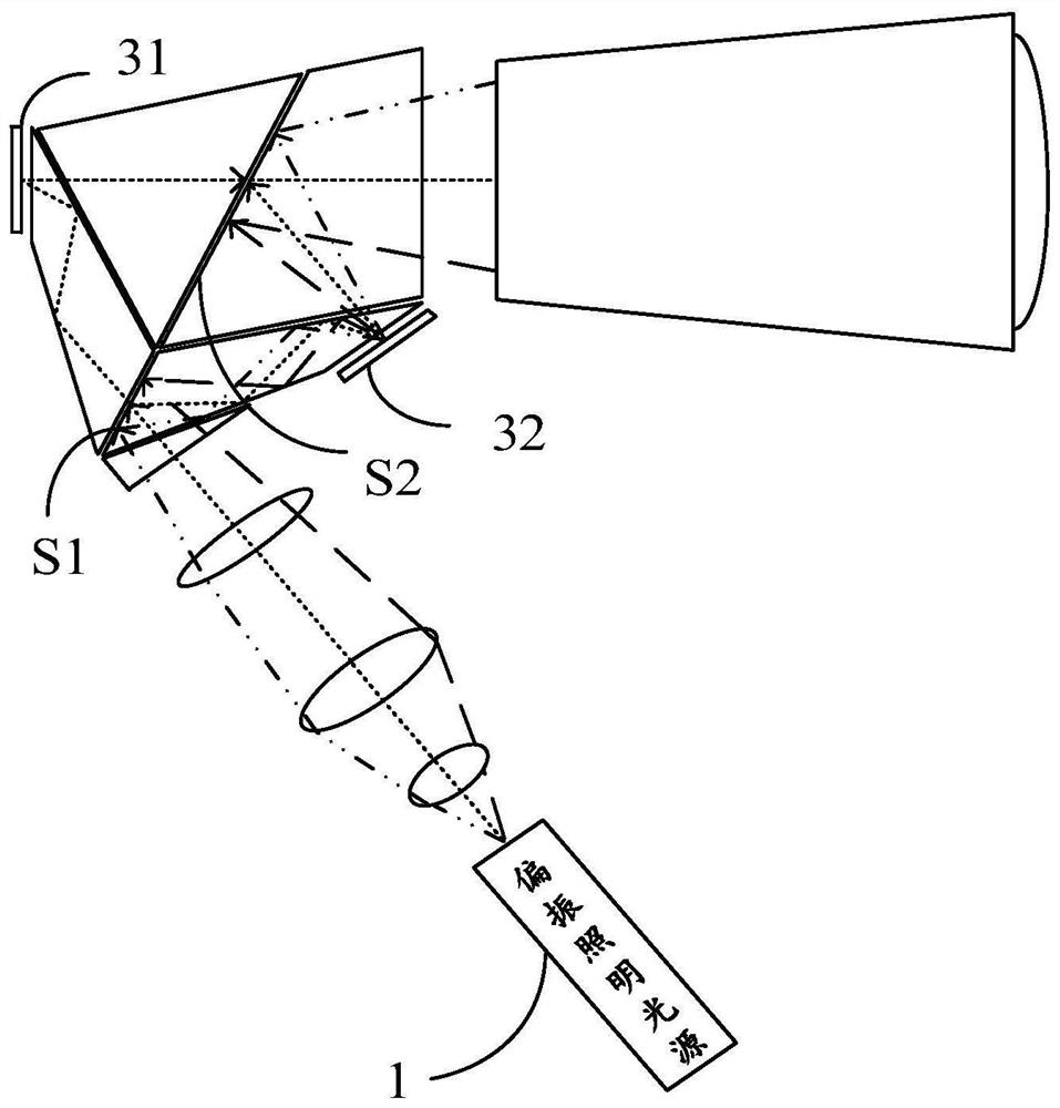
[0050] see image 3 , image 3 It is a schematic structural diagram of the second embodiment of the projection optical system of the present application. On the basis of the first embodiment, the light source 1 in this embodiment can be set as a polarized illumination light source. When the projection optical system of this embodiment splits and combines polarized illumination light, it can also realize lossless light effect.
[0051] In the dielectric material, because the transmittance of the two polarization states of S light and P light is different, the transmittance curves of the dielectric film layer for S light and P light are different. Even if the incident angle remains the same, the transmittance The curves are also separated from each other. for example Figure 4 As shown, P25 is the transmittance curve when the incident angle of P light is 25 degrees, S25 is the transmittance curve when the incident angle of S light is 25 degrees; P13 is the transmittance curve...
no. 1 example
[0053] Different from the first embodiment, the beam splitting surface S1 in this embodiment divides any sub-beam in the illumination beam into a first sub-beam and a second sub-beam according to polarization characteristics. Specifically, the first sub-beam is P-polarized light, and the second sub-beam is S-polarized light. The splitting surface S1 transmits P-polarized light and reflects S-polarized light.
[0054] The light-combining surface S2 synthesizes the first sub-beam emitted by the first spatial light modulator 31 and the second sub-beam emitted by the second spatial light modulator 32 according to the polarization characteristics, and then emits the output beam. Specifically, the light-combining surface S2 synthesizes the P-polarized light emitted by the first spatial light modulator 31 and the S-polarized light emitted by the second spatial light modulator into an outgoing light beam and then emits it.
[0055] For other specific structures of the light splitting...
PUM
 Abstract
Description
Claims
Application Information
 - R&D
- Intellectual Property
- Life Sciences
- Materials
- Tech Scout
- Unparalleled Data Quality
- Higher Quality Content
- 60% Fewer Hallucinations
Browse by: Latest US Patents, China's latest patents, Technical Efficacy Thesaurus, Application Domain, Technology Topic, Popular Technical Reports.
© 2025 PatSnap. All rights reserved.Legal|Privacy policy|Modern Slavery Act Transparency Statement|Sitemap|About US| Contact US: help@patsnap.com