

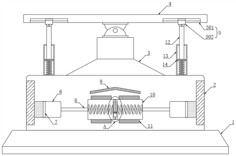
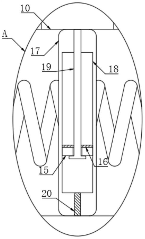
Low-latitude city automatic light following type photovoltaic power generation panel mounting structure
A photovoltaic power generation panel and installation structure technology, applied in the direction of photovoltaic power generation, photovoltaic module support structure, photovoltaic module, etc., can solve the problem that the luminous effect of photovoltaic panels cannot be kept in the best state, and achieve the effect of improving power generation efficiency
- Summary
- Abstract
- Description
- Claims
- Application Information
AI Technical Summary
Problems solved by technology
Method used
Image

Examples
Embodiment Construction
[0020] The following will clearly and completely describe the technical solutions in the embodiments of the present invention with reference to the accompanying drawings in the embodiments of the present invention. Obviously, the described embodiments are only some, not all, embodiments of the present invention.
[0021] In describing the present invention, it should be understood that the terms "upper", "lower", "front", "rear", "left", "right", "top", "bottom", "inner", " The orientation or positional relationship indicated by "outside", etc. is based on the orientation or positional relationship shown in the drawings, and is only for the convenience of describing the present invention and simplifying the description, rather than indicating or implying that the referred device or element must have a specific orientation, so as to Specific orientation configurations and operations, therefore, are not to be construed as limitations on the invention.
[0022] refer to Figure ...
PUM
 Abstract
Description
Claims
Application Information