Universal mechanical connection and spinning fixing device for aluminum squares

A general-purpose machine and fixing device technology, applied in the field of aluminum alloys, can solve the problems of cumbersome manual operation, limited dimensions and specifications of aluminum squares, affecting the appearance, and achieve the effect of reducing work intensity, eliminating potential safety hazards, and ensuring aesthetics.

Inactive Publication Date: 2021-03-09
温州根旭电子科技有限公司
View PDF0 Cites 0 Cited by
  • Summary
  • Abstract
  • Description
  • Claims
  • Application Information

AI Technical Summary

Problems solved by technology

[0002] Aluminum square is a widely used ceiling material. During the installation of aluminum square, due to the limited size and specifications of aluminum square, when the building needs to install aluminum square with different lengths, it is usually necessary to manually install part of the aluminum square. If the welding method is used, the weld seam will be easily left, which will affect the appearance. The manual use of short aluminum square as the intermediate connection can ensure a certain aesthetics. When the manual operation is more cumbersome, on the other hand, Due to the high elasticity of the aluminum alloy material, the tightness of the mechanical installation of the aluminum baffle is not high. At the same time, because the material at the connection of the aluminum baffle is less, the stability of the connection is not high, and there are certain safety hazards.

Method used


Image

  • Universal mechanical connection and spinning fixing device for aluminum squares
  • Universal mechanical connection and spinning fixing device for aluminum squares
  • Universal mechanical connection and spinning fixing device for aluminum squares

Examples


Embodiment Construction

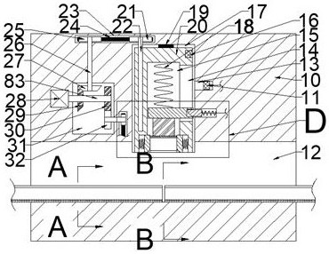
[0019] Combine below Figure 1-6 The present invention is described in detail, wherein, for the convenience of description, the orientations mentioned below are defined as follows: figure 1 The up, down, left, right, front and back directions of the projection relationship itself are the same.

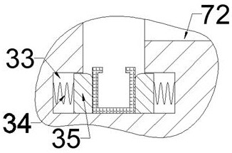
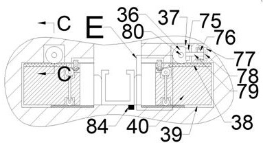
[0020]A general-purpose aluminum square mechanical connection and spinning fixing device described in conjunction with accompanying drawings 1-6 includes a main box body 10, and a left and right through processing cavity 12 is provided inside the main box body 10, and the front of the processing cavity 12 is The side communicates with a forward through chamber 72 with an opening forward. The processing chamber 12 communicates with two mutually symmetrical compacting movable chambers 39, and the left and right end walls of the compacting movable chamber 39 are slidably connected to each other. Compression slide 40, said compression slide 40 upper surface is fixedly connected with the r...


PUM


Abstract

The invention relates to the related field of aluminum alloys, and discloses a universal mechanical connection and spinning fixing device for aluminum squares. The universal mechanical connection andspinning fixing device comprises a main box, a left-right through machining cavity is formed in the main box, a forward through cavity with a forward opening is formed in the front side of the machining cavity in a communicating mode, and two symmetric pressing movable cavities are formed in the front and rear parts of the machining cavity in a communicating mode. A pressing sliding seat is connected between the left end wall and the right end wall of the pressing movable cavity in a sliding fit mode, a pressing rack is fixedly connected into the upper end face of the pressing sliding seat, apressing gear cavity is formed in the upper side of the pressing movable cavity in a communicating mode, a lifting box drives the connecting aluminum squares to move downwards to make contact with thealuminum squares to be jointed, and the working intensity of workers is reduced. A grinding tool for installation drives the connecting aluminum squares to move downwards to be inserted into the aluminum squares to be jointed, so that automatic jointing of the aluminum squares is achieved, the attractiveness of aluminum square installation is guaranteed, a half gear ring drives a spinning plate to rotate, the spinning plate achieves spinning of materials at the joint of the aluminum squares, and therefore the stability of aluminum square connection is improved.

Description

technical field [0001] The invention relates to the related fields of aluminum alloys, in particular to a universal mechanical connection and spinning fixing device for aluminum squares. Background technique [0002] Aluminum square is a widely used ceiling material. During the installation of aluminum square, due to the limited size and specifications of aluminum square, when the building needs to install aluminum square with different lengths, it is usually necessary to manually install part of the aluminum square. If the welding method is used, the weld seam will be easily left, which will affect the appearance. The manual use of short aluminum square as the intermediate connection can ensure a certain aesthetics. When the manual operation is more cumbersome, on the other hand, Due to the high elasticity of the aluminum alloy material, the tightness of the mechanical installation of the aluminum baffle is not high. At the same time, because the material at the connection ...

Claims


Application Information

Patent Timeline
Patent Type & Authority Applications(China)
IPC IPC(8): B21D39/00E04B9/10
CPCB21D39/00E04B9/10
Inventor 赵国庆
Owner 温州根旭电子科技有限公司
Why Eureka
Try Eureka