Drying temporary storage machine

A caching machine and drying technology, which is applied in the direction of conveyor objects, conveyor control devices, pretreatment surfaces, etc., can solve the problems of long length of double-speed chain conveyor line, large site occupation area, and slow speed, so as to save floor space , Guaranteed output, extended motion stroke effect

Pending Publication Date: 2021-03-09
东莞市爱康智能技术有限公司
View PDF4 Cites 1 Cited by
  • Summary
  • Abstract
  • Description
  • Claims
  • Application Information

AI Technical Summary

Problems solved by technology

[0003] The existing drying buffer machine includes a carrier positioning device and a double-speed chain conveyor line. Multiple carrier positioning devices are arranged along the conveying track array of the double-speed chain conveyor. The carrier is placed on the carrier positioning device, and the double-speed chain conveyor line drives the carrier positioning device to drive the bottom shell and glass plate to move through the carrier to achieve natural air drying. After the natural air drying is completed, the carrier needs to be manually taken out of the carrier positioning device , the natural air-drying speed is slow, in order to increase the output by adding a carrier positioning device, the length of the double-speed chain conveyor line is very long, and the site occupies a large area

Method used


Image

  • Drying temporary storage machine
  • Drying temporary storage machine
  • Drying temporary storage machine

Examples


Embodiment Construction

[0021] The present invention will be further described below in conjunction with accompanying drawing:

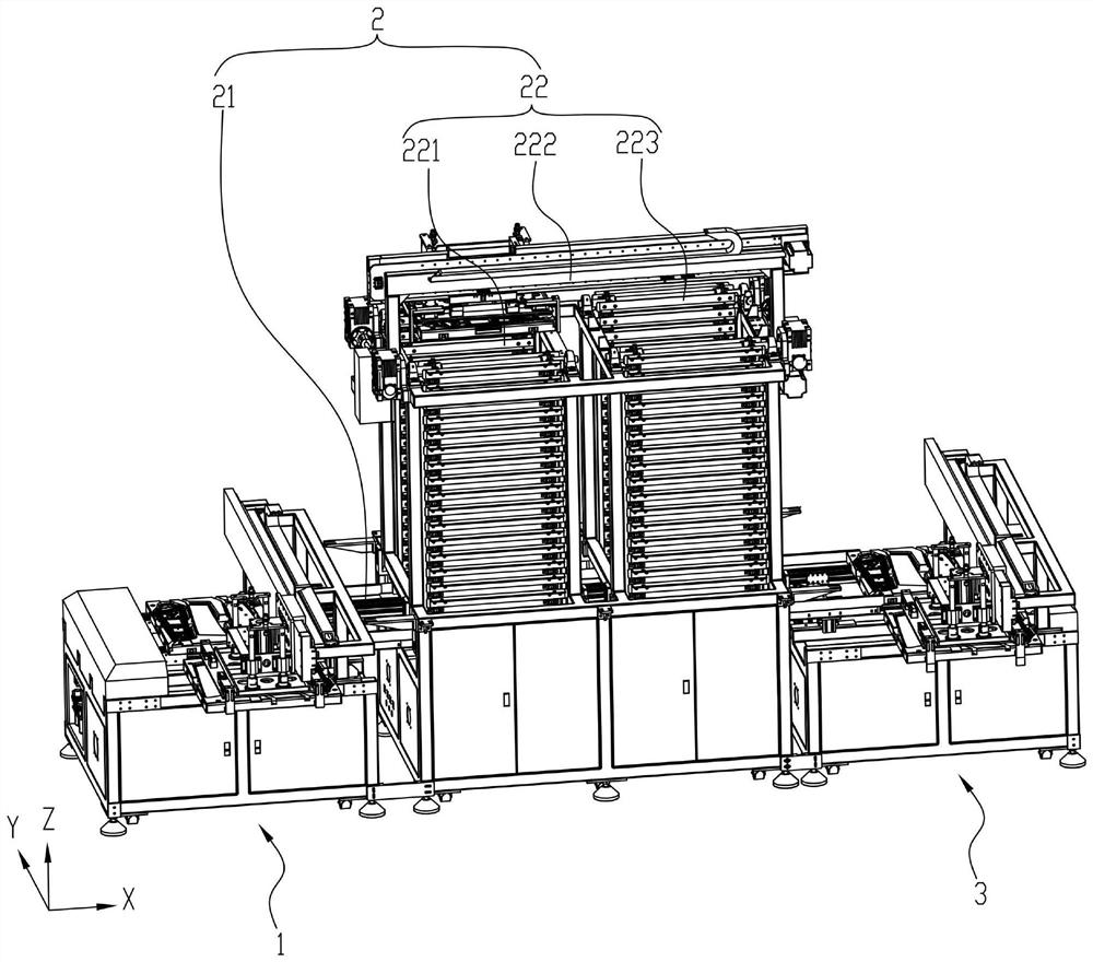
[0022] Please refer to figure 1 , a drying cache machine, including a feeding device 1, a natural air-drying device 2 and a feeding device 3, the natural air-drying device 2 is located between the feeding device 1 and the unloading device 3, and the natural air-drying device 2 is arrayed along the X-axis First, the natural air-drying equipment 2 includes an X-axis conveying device 21 and a vertical trajectory conveying device 22. The vertical trajectory conveying device 22 is arranged on the X-axial conveying device 21. The material mechanism 222 and the circulating lowering mechanism 223, the circulating lifting mechanism 221 and the circulating lowering mechanism 223 are successively arranged on the X-axis conveying device 21 along the conveying direction of the X-axis conveying device 21, and the material-transporting mechanism 222 is arranged across the X-axis On the c...


PUM


Abstract

The invention provides a drying temporary storage machine. The drying temporary storage machine comprises a feeding device, a natural air drying device and a discharging device, wherein the natural air drying device is located between the feeding device and the discharging device and comprises an X-axis conveying device and an n-shaped track conveying device, and the n-shaped track conveying device comprises a circulating lifting mechanism, a material carrying mechanism and a circulating descending mechanism, the circulating lifting mechanism and the circulating descending mechanism are sequentially arranged on the X-axis conveying device in the conveying direction of the X-axis conveying device, and the material carrying mechanism is arranged on the circulating lifting mechanism and the circulating descending mechanism in a crossing mode in the X-axis direction. According to the drying temporary storage machine, automatic feeding and automatic discharging are achieved through the feeding device and the discharging device correspondingly, materials are conveyed in and out of the n-shaped track conveying device through the X-axis conveying device, the n-shaped track conveying devicecontains the multiple materials through the longitudinal space and drives the multiple materials to move along the n-shaped track by the n-shaped track conveying device, the movement stroke of the materials is prolonged, the occupied area is saved, and the yield is ensured.

Description

technical field [0001] The invention relates to the field of drying equipment, in particular to a drying cache machine for realizing natural air drying. Background technique [0002] With the advancement of technology, the electronic products installed on the car are becoming more and more abundant. There is a display device installed on the B-pillar of the car, which includes a bottom case and a glass plate. During the production process of the bottom case and the glass plate, the The bottom shell and the glass plate of the primer spraying process need to undergo a natural air drying process together, which is completed by a drying cache machine. [0003] The existing drying buffer machine includes a carrier positioning device and a double-speed chain conveyor line. Multiple carrier positioning devices are arranged along the conveying track array of the double-speed chain conveyor. The carrier is placed on the carrier positioning device, and the double-speed chain conveyor...

Claims


Application Information

Patent Timeline
IPC IPC(8): B65G47/90B65G47/88B65G47/57B65G47/42B65G43/10B65G43/08B05D3/04
CPCB65G47/901B65G47/8815B65G47/42B65G47/57B65G43/10B65G43/08B05D3/0406
Inventor 周先进庾健彬
Owner 东莞市爱康智能技术有限公司
Why Eureka
Try Eureka