Fabricated steel-concrete combined rigid frame bridge and construction method thereof

A prefabricated, rigid-frame bridge technology, applied in the direction of erecting/assembling bridges, bridges, bridge parts, etc., can solve the problems of increasing the traffic interference of the lower roads, increasing the investment of construction units, and increasing the workload on site, so as to reduce the Use less steel, improve aesthetics, and facilitate construction

Pending Publication Date: 2021-03-09
GUANGZHOU MUNICIPAL ENG DESIGN & RES INST CO LTD
View PDF0 Cites 1 Cited by
  • Summary
  • Abstract
  • Description
  • Claims
  • Application Information

AI Technical Summary

Problems solved by technology

The commonly used design method of prefabricated steel-concrete composite continuous beams at this stage is to set the main beam as a longitudinal segmental member, and a large-scale cover beam structure is required, which increases the height of the structure, increases the construction cost, and greatly reduces the aesthetics.
In addition, the splicing between segments is realized through the support of temporary piers on site. The installation time of temporary piers usually runs through the whole process of bridge construction, which increases the interference of construction on the road below and increases the investment of construction units.
However, after the steel beams are constructed first, the concrete layer is poured on site. Although the temporary piers are removed after the steel beam splicing is completed, a large number of formworks need to be erected on site, which increases the workload on site. The characteristics of post-combination with concrete lead to an increase in the amount of steel used in the structure

Method used


Image

  • Fabricated steel-concrete combined rigid frame bridge and construction method thereof
  • Fabricated steel-concrete combined rigid frame bridge and construction method thereof
  • Fabricated steel-concrete combined rigid frame bridge and construction method thereof

Examples


Embodiment Construction

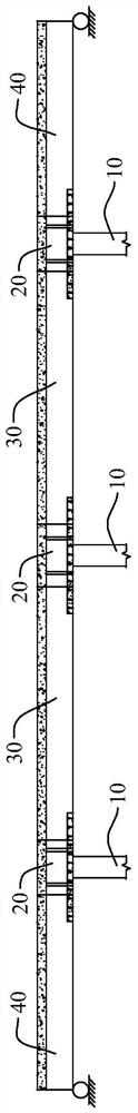
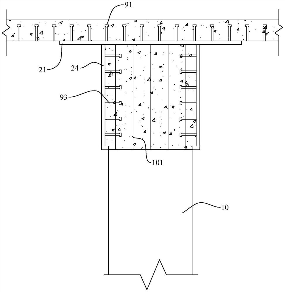
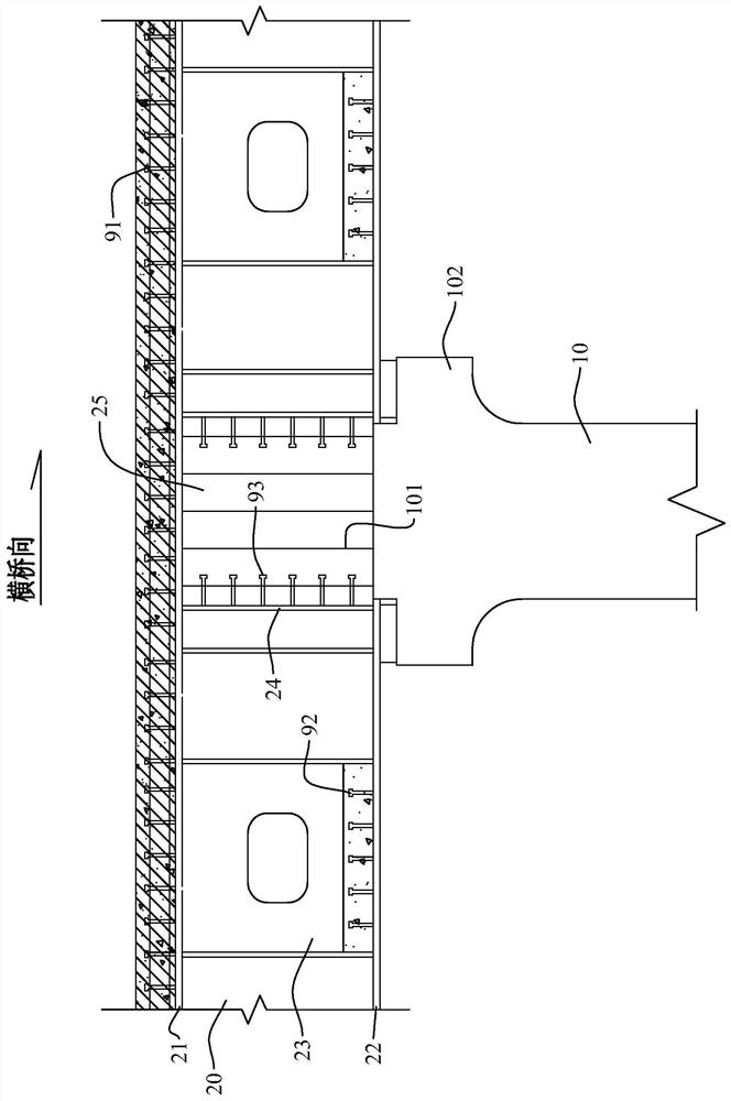
[0036] refer to Figure 1 to Figure 8 , the embodiment of the present invention provides an assembled steel-concrete composite rigid frame bridge, the assembled steel-concrete composite rigid frame bridge includes several prefabricated main girder segments, pier columns 10, prefabricated beams 20, longitudinal connecting sections 50 and transverse connecting sections 60.

[0037]The prefabricated main beam section can be divided into a prefabricated end section 40 and a prefabricated middle beam section 30 , and the prefabricated main beam section is mainly composed of steel beams, concrete slabs and several roof shear connectors 91 . The concrete slab is located above the top slab 21, and one end of the top slab shear connector 91 is welded on the top slab 21, and the other end is integrated with the main beam after pouring the concrete slab. The steel girder is mainly composed of a top plate 21, a bottom plate 22 and two web plates 23 welded together.

[0038] At the same ...


PUM


Abstract

The invention discloses a fabricated steel-concrete combined rigid frame bridge and a construction method thereof. The fabricated steel-concrete combined rigid frame bridge comprises a plurality of prefabricated main beam sections, pier columns, prefabricated cross beams, longitudinal connecting sections and transverse connecting sections, and the prefabricated cross beams are arranged above the pier columns and are provided with slotted holes; exposed steel bars are arranged above the pier columns and are inserted into the slotted holes, and high-strength concrete grout is poured into the slotted holes to achieve connection of the prefabricated cross beams and the pier columns; and the prefabricated cross beams are connected with the prefabricated middle beam sections and the prefabricated end sections through bolting and welding, the prefabricated steel-concrete combined rigid frame bridge is convenient to prefabricate, transport and construct, the structural advantages of the steel-concrete combined beam can be brought into full play, and industrial production, segmented transportation and prefabricated construction can be achieved.

Description

technical field [0001] The invention relates to the technical field of bridges, in particular to an assembled steel-concrete composite rigid frame bridge and a construction method thereof. Background technique [0002] With the acceleration of the urbanization process, the construction of municipal infrastructure has gradually entered a climax, while the traditional cast-in-place construction will easily lead to a sudden drop in the traffic capacity of the construction area, affecting the smooth flow and safety of the road, and even frequent traffic interruptions, which greatly affect the life of residents. work and life; in addition, the traditional cast-in-place site has a large amount of work, low construction efficiency, high overall energy consumption, and serious disturbance to the residents. The prefabricated bridge can significantly speed up the construction progress and reduce the impact on the existing Traffic interference, and is conducive to environmental protect...

Claims


Application Information

Patent Timeline
Patent Type & Authority Applications(China)
IPC IPC(8): E01D19/00E01D19/02E01D19/06E01D21/00E01D101/26E01D101/30
CPCE01D19/00E01D19/02E01D19/06E01D21/00E01D2101/26E01D2101/30
Inventor 宁平华王晟刘剑蔡晓鹏曾炯坤范骏鹏熊洪波郭玉平
Owner GUANGZHOU MUNICIPAL ENG DESIGN & RES INST CO LTD
Why Eureka
Try Eureka