Large-torque hydraulic motor crankshaft

A hydraulic motor and high torque technology, which is applied in the design field of hydraulic motor crankshaft, can solve the problems of large system loss, low utilization rate of oil source pressure, and decreased efficiency of hydraulic motor, so as to achieve large starting torque, ensure motion transmission accuracy, The effect of simplifying the structure of the motor

Pending Publication Date: 2021-03-09
SICHUAN LINGFENG AVIATION HYDRAULIC MACHINERY
View PDF0 Cites 0 Cited by
  • Summary
  • Abstract
  • Description
  • Claims
  • Application Information

AI Technical Summary

Problems solved by technology

The disadvantage is that the hydraulic motor must have sufficient back pressure at the oil return port to ensure normal operation, and the higher the speed, the greater the back pressure required. The increase in back pressure means that the pressure utilization rate of the oil source is low, and the system's big loss
However, excessively increasing the back pressure will significantly reduce the efficiency of the hydraulic motor

Method used


Image

  • Large-torque hydraulic motor crankshaft
  • Large-torque hydraulic motor crankshaft

Examples


Embodiment Construction

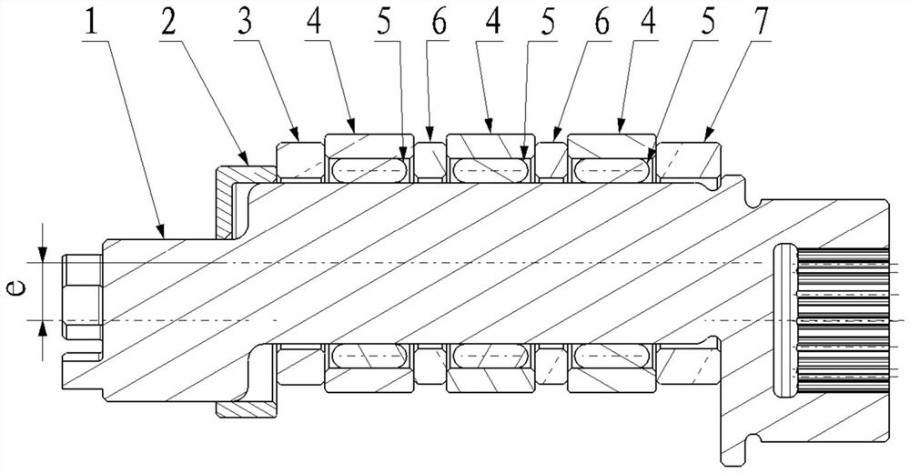
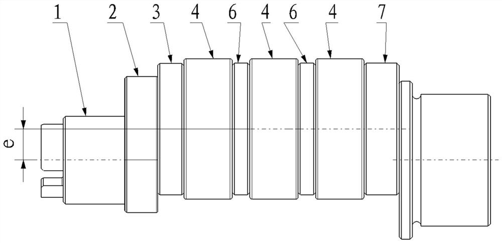
[0016] refer to Figure 1 ~ Figure 2 . In the preferred embodiment described below, a high-torque hydraulic motor crankshaft includes: a crankshaft 1 sealed in a housing through an end cover 2, and the extended end of the crankshaft 1 is the output shaft of the motor. The eccentric crank neck end of the crankshaft 1 and the eccentric wheel shaft end of the coaxial connecting rod are supported on the bearings of the end cover 2 and the rear end cover of the housing through a pair of tapered roller bearings, and rotate around the central axis of rotation of the bearings to limit the crankshaft 1 degrees of freedom of horizontal, up and down, forward and backward reciprocating motion, on the crankshaft 1 between the eccentric crank neck end and the eccentric shaft end, a pressure ring 4 that bears hydraulic pressure and a roller mounted in the pressure ring 4 are equipped. Needle 5, and each pressure ring 4 is arranged at intervals through the spacer ring 6, distributed in a lin...


PUM


Abstract

The invention discloses a large-torque hydraulic motor crankshaft. By means of the large-torque hydraulic motor crankshaft, the starting torque and the transmission torque of a motor can be improved.According to the technical scheme, by means of the eccentric bent neck end of the motor crankshaft and an eccentric wheel shaft connected with a coaxial connecting rod, the degree of freedom of horizontal, vertical and front-back reciprocating motion of the crankshaft is limited, pressing rings for bearing hydraulic pressure and roller pins assembled in the pressing rings are assembled at the position, between the eccentric bent neck end and the eccentric wheel shaft end, of the crankshaft, the pressing rings are arranged at intervals through spacer rings and distributed between positioning spacer rings and baffle rings in a linear array manner, it is guaranteed that the roller pins make contact with the pressing rings all the time in the working process of the crankshaft, an axial positioning effect is achieved on the roller pins, and a static pressure balance structure is formed between the roller pins and a crankshaft motion pair; and hydraulic force applied to the pressing rings generates the torque enabling the crankshaft to rotate through the eccentric distance e of the crankshaft, and the roller pins convert a sliding friction motion pair between the inner surfaces of the pressing rings and the outer surface of the crankshaft into a rolling friction motion pair. Reliability of stable transmission efficiency and precision is ensured.

Description

technical field [0001] The invention relates to a hydraulic motor mainly used in injection molding machinery, ships, hoists, engineering machinery, construction machinery, coal mining machinery, mining machinery, metallurgical machinery, ship machinery, petrochemical industry, port machinery, etc. It specifically relates to the design of hydraulic motor crankshafts. Background technique [0002] A hydraulic motor is an actuator of a hydraulic system and a device that converts hydraulic pressure energy into mechanical energy. It converts the hydraulic pressure energy provided by the hydraulic pump into the mechanical energy (torque and speed) of its output shaft. Liquids are media that transmit force and motion. Hydraulic motors, also known as oil motors, require forward and reverse rotation, and their structure is symmetrical. The function of the hydraulic motor is to convert hydraulic energy into mechanical energy, the crankshaft is the output end of the hydraulic motor,...

Claims


Application Information

Patent Timeline
Patent Type & Authority Applications(China)
IPC IPC(8): F03C1/00F03C1/02
CPCF03C1/002F03C1/02
Inventor 杨宁都苟辽王力
Owner SICHUAN LINGFENG AVIATION HYDRAULIC MACHINERY
Why Eureka
Try Eureka