Thermally driven resonant micropump

A thermally driven and resonant technology, applied in the direction of variable displacement pump components, pumps with flexible working elements, pumps, etc., can solve the problems of high cost, high processing difficulty, difficult to prepare piezoelectric materials, etc., to reduce processing costs, Optimizing the machining process, the effect of constant fluid flow

Pending Publication Date: 2021-03-09
无锡费曼科技有限公司
View PDF0 Cites 0 Cited by
  • Summary
  • Abstract
  • Description
  • Claims
  • Application Information

AI Technical Summary

Problems solved by technology

[0003] In the prior art, the piezoelectric drive is usually used to accelerate the fluid in the tiny channel. The piezoelectric material needs to control the crystal orientation. However, due to the limitation of the existing production technology, the piezoelectric material is not easy to prepare, the cost is high, and the processing is difficult.

Method used


Image

  • Thermally driven resonant micropump
  • Thermally driven resonant micropump
  • Thermally driven resonant micropump

Examples


Embodiment

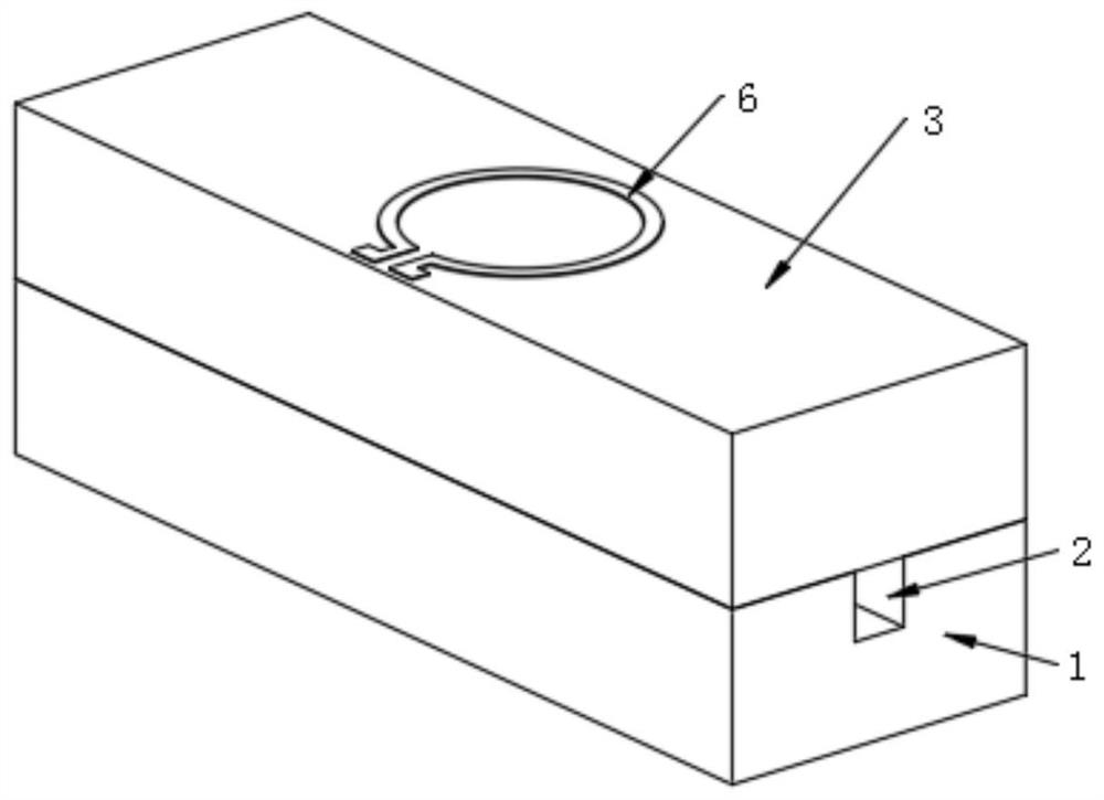
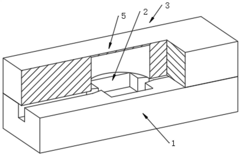
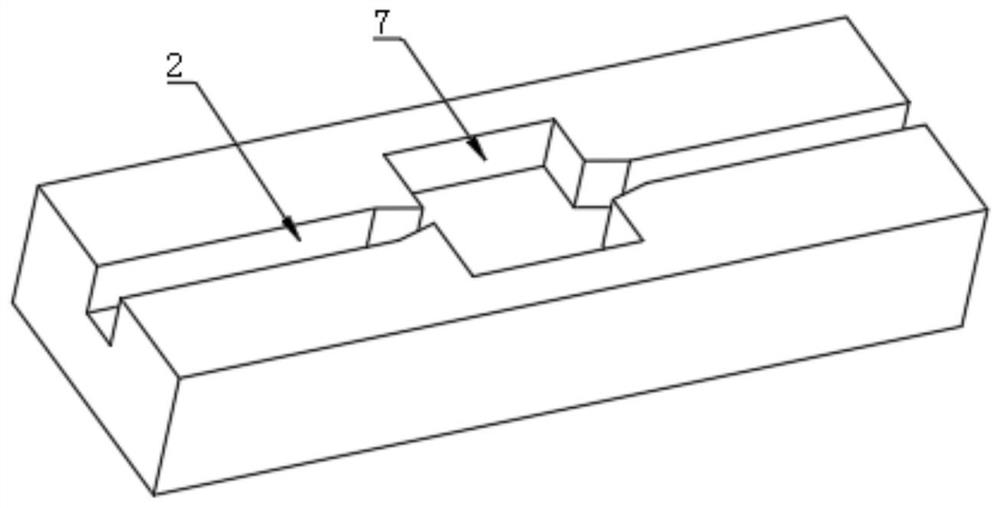
[0030] EXAMPLES: A thermally driven resonant micropump, such as figure 1 with figure 2 As shown, including the substrate 1, the upper surface of the substrate 1 is provided with the flow path 2 for the microfluid through the microfluid, and the substrate 1 is provided with a cover 3 for the closure flow path 2, and passed over the block 3 Eroching forming cavity 4, cavity 4 communication passage 2, unclosed substrate 1 of the cavity 4 above the upper surface of the diaphragm 5, the upper surface of the diaphragm 5 is provided with a hot wire 6, the thickness of the diaphragm 5 is 10 -200um.

[0031] When the microfluid is passed through the flow path 2, the cycle voltage is applied to the electric wire 6 with a frequency F0, and the heat transfer output of the frequency F0 generates the frequency F0, the diaphragm 5 is heat-generating periodic thermal stress of the frequency F0, when the thermal stress When the frequency F0 is close to the inherent frequency f1 of the vibrating ...


PUM


Abstract

The invention relates to a resonant micropump. The resonant micropump has the effects of being simple in structure, easy to machine and low in cost. The invention discloses the thermally driven resonant micropump. The thermally driven resonant micropump comprises a substrate, wherein the upper surface of the substrate is provided with a flow channel for microfluid to pass through in the length direction of the substrate, the substrate is provided with a sealing cover used for sealing the flow channel, a cavity is formed in the sealing cover through etching, and the cavity is communicated withthe flow channel; and a vibrating diaphragm is formed on a non-etched substrate part above the cavity, and an electric heating wire is arranged on the upper surface of the vibrating diaphragm. By cooperation of the flow channel, the vibrating diaphragm and the electric heating wire, thermal driving fluid acceleration is achieved, the machining cost is reduced, and the machining process is optimized.

Description

Technical field [0001] The present invention relates to a resonant micropump, more specifically, involving a heat-driven resonant micropump. Background technique [0002] Today's microfluidic technology has great development potential and broad prospects in terms of disease testing, ingredient analysis, because of the advantages of high integration, high sensitivity, high flux, reagent consumption. Microfluidic techniques need to drive liquid flow in a small channel. Conventional microfluidic technology does not have the active drive function of the liquid in the microoflow, and the fluid in the micro track mainly rely on capillary force. However, in terms of mixing of fluid reagents, the fluid is still needed to accelerate. [0003] In the prior art, a piezoelectric drive is usually used to accelerate fluid in the microchannel, and the piezoelectric material is to control crystal, but due to the limitation of the existing production technology, the piezoelectric material is not ...

Claims


Application Information

Patent Timeline
Patent Type & Authority Applications(China)
IPC IPC(8): F04B43/04F04B53/16
CPCF04B43/043F04B53/16
Inventor 周旭波王扬华于葛亮任晓栋
Owner 无锡费曼科技有限公司
Why Eureka
Try Eureka