Charging gun system control circuit

A technology for controlling circuits and charging guns, applied to battery circuit devices, circuit devices, circuit monitoring/indication, etc., can solve problems such as inability to reach driving current, failure of relays to pull in, charging failures, etc., and achieve reliable detection results and convenient control. And the effect of accurate, not easy waveform false detection

Active Publication Date: 2021-03-09
XIAMEN Z&H ELECTRONICS TECH
View PDF4 Cites 1 Cited by
  • Summary
  • Abstract
  • Description
  • Claims
  • Application Information

AI Technical Summary

Problems solved by technology

[0004]The existing charging gun control circuit pulls the triode through the I / O port of the microcontroller to drive the MOS tube, and then turns on the relay to control the charging, but in a special geographical environment For example, the outdoor temperature in winter in the north can reach -40°C. In such a low temperature environment, the driving current needs to reach 400mA~500mA. The existing control circuit structure cannot reach this driving current, resulting in the failure of the relay to pull in, resulting in charging. Fault

Method used


Image

  • Charging gun system control circuit
  • Charging gun system control circuit
  • Charging gun system control circuit

Examples


Embodiment Construction

[0033] In order to make the object, technical solution and advantages of the present invention clearer, the present invention will be further described in detail below in conjunction with the accompanying drawings and embodiments.

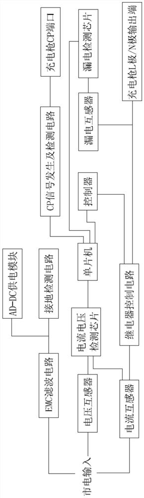
[0034] Such as figure 1 As shown, the present invention discloses a charging gun system control circuit, which is characterized in that it includes an EMC filter circuit 100, an AC-DC power supply module 200, a ground detection circuit 300, a single-chip microcomputer U3, a controller U18, a relay control circuit 400, a detection Circuit 500, CP signal generation and detection circuit.

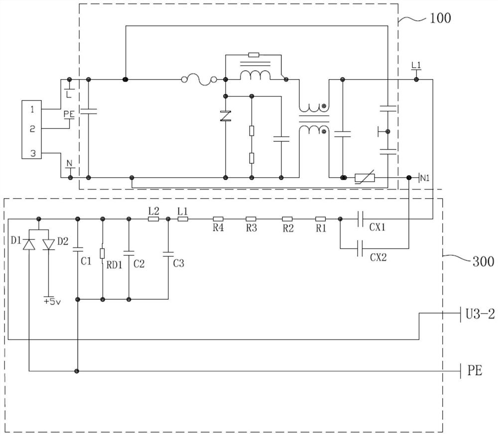
[0035] Such as figure 2 As shown, the power input terminal of the charging gun is connected to the mains, of which port 1 is connected to the live wire L of the power supply, port 2 is connected to the neutral wire N of the power supply, and port 3 is connected to the PE ground wire. After passing through the EMC filter circuit 100, the output terminals are the ...


PUM


Abstract

The invention discloses a charging gun system control circuit, which comprises an AC-DC power supply module, a single chip microcomputer, a controller and a relay control circuit, wherein the AC-DC power supply module is connected with commercial power to supply power to the single chip microcomputer, the controller and the relay control circuit; a relay control pin is arranged on the single chipmicrocomputer, and the input end of the controller is connected with the relay control pin. The relay control circuit comprises a relay K1, a relay K2, a diode D1 and a diode D2, positive electrodes of primary coils of the relay K1 and the relay K2 are connected with the AC-DC power supply module, and negative electrodes of the primary coils are connected with an output pin of the controller; oneend of a secondary coil of the relay K1 is connected with a power live wire L, and the other end is connected with a charging gun L-pole output end; one end of a secondary coil of the relay K2 is connected with the power zero line N, and the other end is connected with the N-pole output end of the charging gun. The switch relay can still be driven at an extremely low temperature, the adaptabilityis good, and control is more convenient and accurate.

Description

technical field [0001] The invention relates to the technical field of charging, in particular to a charging gun system control circuit. Background technique [0002] As the energy supply station for the operation of electric vehicles, the electric vehicle charging pile is an important supporting infrastructure necessary for the commercialization of electric vehicles. The charging gun is a device on the electric vehicle charging pile that is connected to the mains and supplies power to the electric vehicle. [0003] When charging an existing electric vehicle, insert the charging gun into the on-board charging port to connect with the on-board charger. CP is the control connection line between the charging gun and the on-board charger. After the internal charging control circuit confirms that the signal is normal, the positive voltage of the PWM rectangular wave voltage generated by the CP drops from 12V to 6V, and the negative voltage is -12V. After the charging gun receive...

Claims


Application Information

Patent Timeline
Patent Type & Authority Applications(China)
IPC IPC(8): H02J7/00H02H9/04G01R31/52
CPCH02J7/007192H02J7/00712H02J7/0047H02H9/045G01R31/52Y02T10/70Y02T10/7072Y02T90/14Y02T90/12
Inventor 杨善进张学功颜善茂
Owner XIAMEN Z&H ELECTRONICS TECH
Why Eureka
Try Eureka