

Textile dye mixing device
A mixing device and textile dye technology, applied in the textile field, can solve the problems of block dyes being difficult to crush and affecting the quality of textile products, and achieve the effects of avoiding clogging, increasing strength, and improving collection efficiency
- Summary
- Abstract
- Description
- Claims
- Application Information
AI Technical Summary
Problems solved by technology
Method used
Image

Examples
Embodiment 1
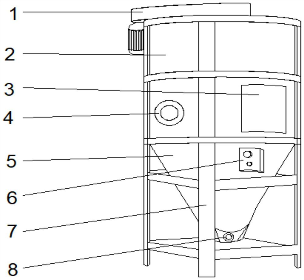
[0035] Such as Figure 1-2, a kind of technical proposal that the present invention proposes: a kind of textile dyestuff mixing device, comprises fixed frame 7, and the inner wall of both sides of fixed frame 7 is fixedly connected with agitating device 2, and the top of agitating device 2 is provided with agitator 1, and agitating device 2 The middle part of the left side of the front is provided with a feed inlet 4, the right side of the front of the stirring device 2 is provided with an observation window 3, the inner walls of both sides of the fixing frame 7 are located at the bottom of the stirring device 2, and a collecting device 5 is arranged on the top of the front of the collecting device 5. A controller 6 is fixedly connected to the right side, and a discharge port 8 is provided at the bottom of the collecting device 5 .
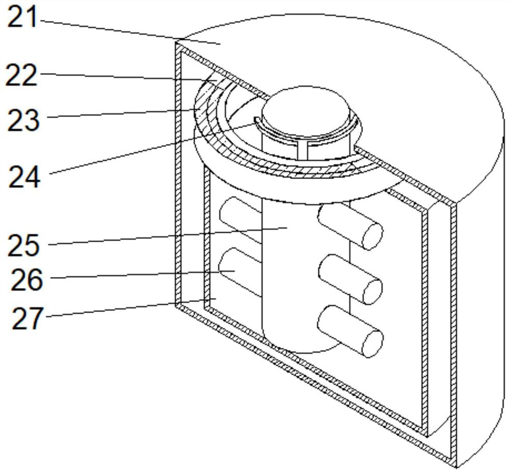
[0036] Wherein, the stirring device 2 comprises a stirring tank 21, the middle position of the inner cavity bottom of the stirring tank 21 is fix...
Embodiment 2
[0040] Such as Figure 1-5 As shown, on the basis of Embodiment 1, the present invention provides a technical solution: the auxiliary mechanism 26 includes a fixed rod 261, the top of the fixed rod 261 is provided with a fixed shaft 262, and the outer surface of the fixed shaft 262 is fixedly connected with a toggle shell 266, the top of the inner cavity of the toggle shell 266 is fixedly connected with a support plate 265, the middle part of the left inner wall of the toggle shell 266 is fixedly connected with an elastic block 263, and the middle part of the right inner wall of the toggle shell 266 is provided with a cutting mechanism 264, the cutting mechanism The right side of 264 runs through the dial case 266 and extends to the outside of the dial case 266 .
[0041] Wherein, the cutting mechanism 264 includes a cutting shaft 2641, the top of the cutting shaft 2641 is fixedly connected with a connecting piece 2643, the middle position of the inner cavity bottom of the cut...
Embodiment 3
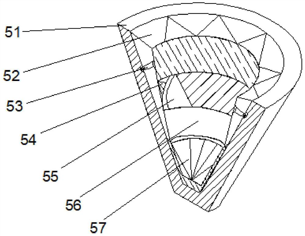
[0044] Such as Figure 1-6 As shown, on the basis of Embodiment 1 and Embodiment 2, the present invention provides a technical solution: the cleaning mechanism 56 includes a plate body 561, a swing plate 563 is arranged on the top of the plate body 561, and the left middle part of the swing plate 563 is fixedly connected Elastic sheet 562 is arranged, and the right side top of swing plate 563 is provided with clearing plate 565, and the middle part of one side of clearing plate 565 close to swing plate 563 is fixedly connected with booster bar 564.
[0045] When in use, inject the dye from the feed port 4, press the start button on the controller 6, the stirrer 1 drives the stirring rod 25 in the stirring device 2 to move, and the rotor on the fixed ring makes the fixed ring close to the stirring rod to stop When working, the adjustment of the stirring rod is more convenient. When working, the fixing ring 24 is away from the stirring rod 25 through the fixing groove 23, which ...
PUM
 Abstract
Description
Claims
Application Information