Painting device for cinerary casket processing

A technology for urns and placing boards, which is applied in the direction of spraying devices, devices for coating liquid on the surface, coatings, etc., and can solve problems such as strong smell, easy to get on the skin, and bad skin

Active Publication Date: 2021-03-12
邳州市鑫盛创业投资有限公司
View PDF10 Cites 3 Cited by
  • Summary
  • Abstract
  • Description
  • Claims
  • Application Information

AI Technical Summary

Problems solved by technology

[0006] In order to overcome the shortcomings of the need for manual repeated dipping and coating, and the strong smell, which is easy to get on the skin and is not good for the skin, the technical problem to be solved by the present invention is to provide a paint that can avoid manual contact with the paint, saving time and effort Painting device for urn processing

Method used


Image

  • Painting device for cinerary casket processing
  • Painting device for cinerary casket processing
  • Painting device for cinerary casket processing

Examples


Embodiment 1

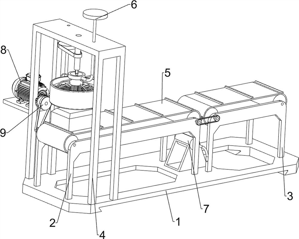
[0025] A kind of painting device for urn processing, such as figure 1 , figure 2 with image 3 As shown, it includes a placement board 1, a long bracket 2, a short bracket 3, a frame 4, a transport assembly 5, a lifting assembly 6 and a painting assembly 7, and the left side of the placement board 1 is connected with a long bracket 2 on the front and rear sides, and the placement board 1. Short brackets 3 are connected to the front and rear sides of the right part. The short bracket 3 is directly to the right of the long bracket 2. The frame 4 is connected to the left side of the top of the placement plate 1. The upper part of the long bracket 2 and the short bracket 3 is rotatably connected to the transportation component 5. The upper part of the frame 4 is slidably connected with a lifting assembly 6, and the middle of the top of the placing plate 1 is connected with a painting assembly 7.

[0026] The transportation assembly 5 includes a first roller 51, a first belt 52,...

Embodiment 2

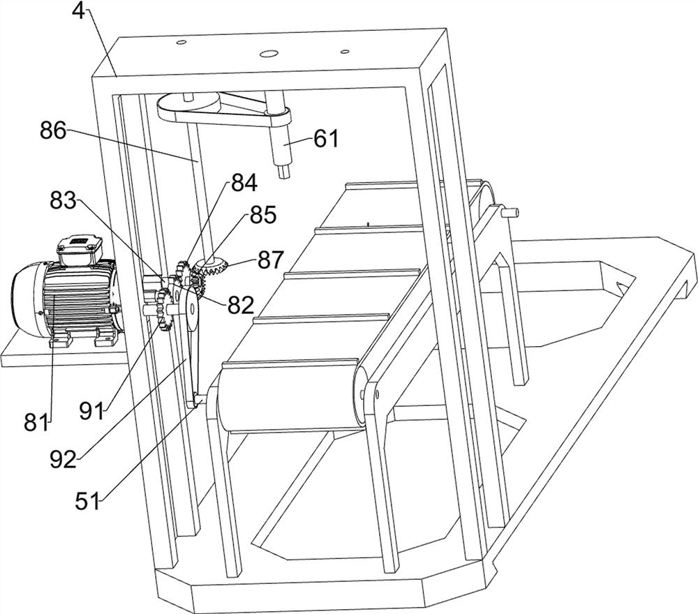
[0031] On the basis of Example 1, such as Figure 4 As shown, a drive assembly 8 is also included, and the drive assembly 8 includes a motor 81, a missing gear 82, a first rotating shaft 83, a first gear 84, a first bevel gear 85, a second rotating shaft 86 and a second bevel gear 87, and the frame 4. A motor 81 is installed on the rear side of the upper part. A missing gear 82 is connected to the output shaft of the motor 81. The rear side of the upper part of the frame 4 is rotatably connected with a first rotating shaft 83. The first rotating shaft 83 is connected with a first gear 84 in the middle. The first gear 84 Mesh with the missing gear 82, the front side of the first rotating shaft 83 is connected with the first bevel gear 85, the upper part of the frame 4 is rotatably connected with the second rotating shaft 86, and the lower part of the second rotating shaft 86 is connected with the second bevel gear 87, the second bevel gear 87 is meshed with the first bevel gear...

Embodiment 3

[0034] On the basis of Example 2, such as Figure 4 As shown, a transmission assembly 9 is also included, the transmission assembly 9 includes a second gear 91 and a transmission belt set 92, the upper rear side of the frame 4 is rotatably connected with a second gear 91, and the second gear 91 meshes with the missing gear 82, A drive belt set 92 is connected between the second gear 91 and the first roller 51 on the left.

[0035] When the missing gear 82 is not meshed with the first gear 84, the missing gear 82 rotates to drive the second gear 91 to rotate, and the second gear 91 rotates to drive the first roller 51 on the left side to rotate, so that there is no need to manually rotate the first roller on the left side 51 transport the urns.


PUM


Abstract

The invention relates to a painting device, in particular to a painting device for cinerary casket processing. The painting device for cinerary casket processing can prevent workers from touching paint and is time-saving and labor-saving. In order to solve the technical problem, the invention provides the painting device for cinerary casket processing. The painting device comprises a placing plate, a long bracket, a short bracket, a frame, a transportation assembly, a lifting assembly and a painting assembly, wherein the placing plate is connected with the long bracket; the long bracket is connected to the placing plate; the short bracket is connected to the placing plate; the frame is connected to the placing plate; the transportation assembly is rotatably connected to the long bracket and the short bracket; the lifting assembly is connected to the frame in a sliding manner; and the painting assembly is connected to the placing plate. According to the painting device, through cooperation of the transportation assembly, the lifting assembly and the painting assembly, a cinerary casket is transported and painted.

Description

technical field [0001] The invention relates to a painting device, in particular to a painting device for urn processing. Background technique [0002] An urn is a container that people use to hold ashes after cremation. The columbarium will be included in the spiritual bone tower for worship. The earliest urn unearthed so far was found in Jerusalem more than 2,000 years ago. Burials were popular in ancient China, and most people were buried in wooden coffins after death. With the development of the times, in order to save resources, ancient coffins have gradually evolved into urns. [0003] At present, people usually spray the paint on the urn by putting the paint upside down in a container, and then manually dip the paint in the container with a brush in hand, and then paint it on the urn. In this way, the paint needs to be manually dipped repeatedly, which is time-consuming. It is laborious and has a strong smell, which is easy to get on the skin and is not good for th...

Claims


Application Information

Patent Timeline
Patent Type & Authority Applications(China)
IPC IPC(8): B05C1/02B05C11/10B05C13/02B05B13/02
CPCB05C1/022B05C11/10B05C13/02B05B13/0221B05B13/0278
Inventor 尤东洋
Owner 邳州市鑫盛创业投资有限公司
Why Eureka
Try Eureka