Full-automatic metal forging forming method

A forging molding, fully automatic technology, applied in the field of forging molding, can solve problems such as manual clamping and turning of workers, and achieve the effect of reducing burden, reducing maintenance cost and increasing service life

Inactive Publication Date: 2021-03-12
谢娟
View PDF0 Cites 0 Cited by
  • Summary
  • Abstract
  • Description
  • Claims
  • Application Information

AI Technical Summary

Problems solved by technology

[0004] Aiming at the deficiencies of the prior art, the present invention provides a fully automatic metal forgi

Method used


Image

  • Full-automatic metal forging forming method
  • Full-automatic metal forging forming method
  • Full-automatic metal forging forming method

Examples


Embodiment 1

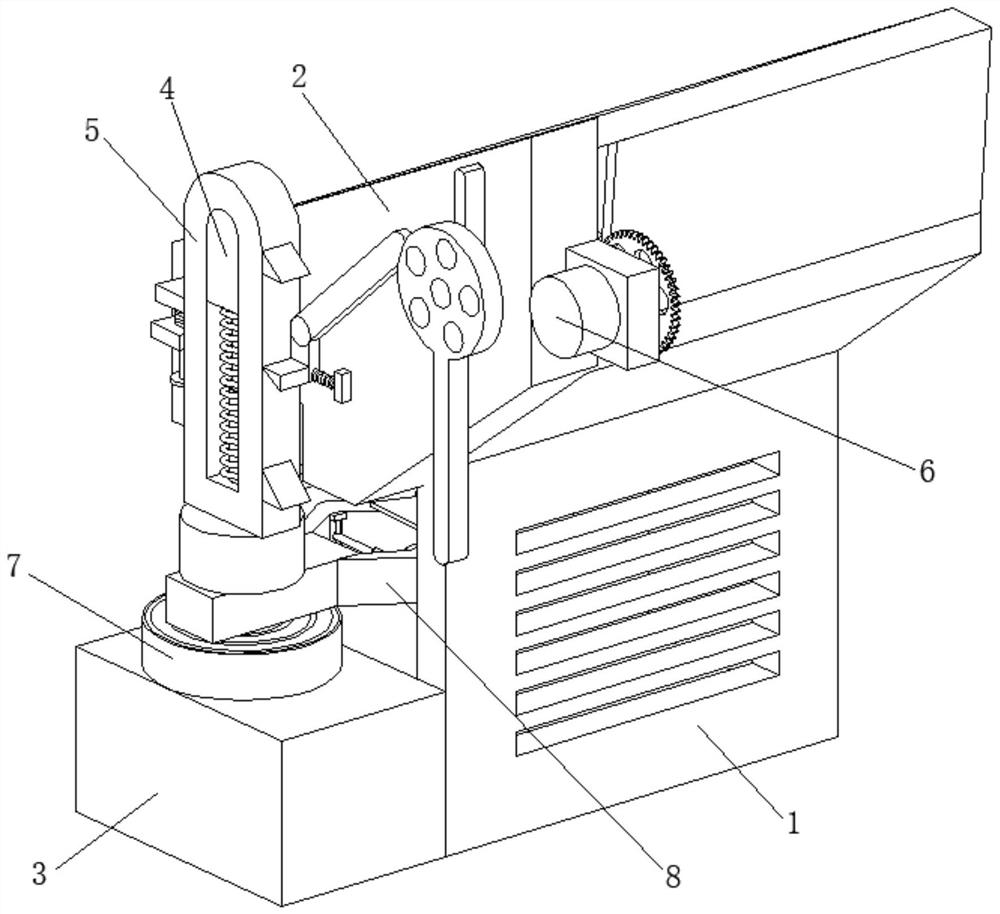
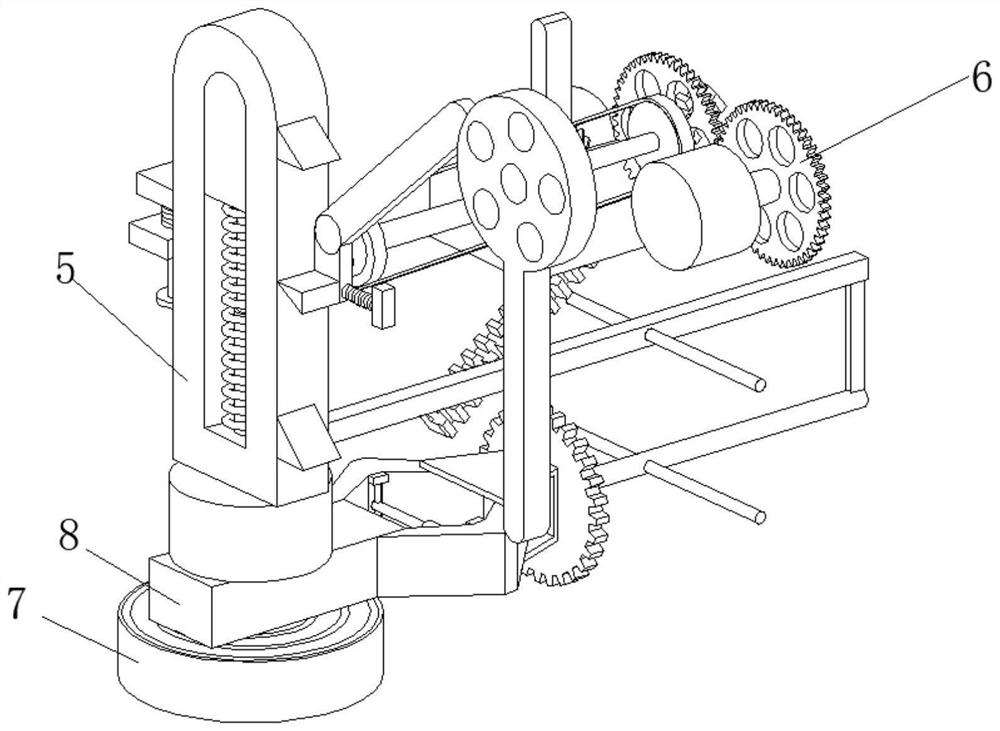
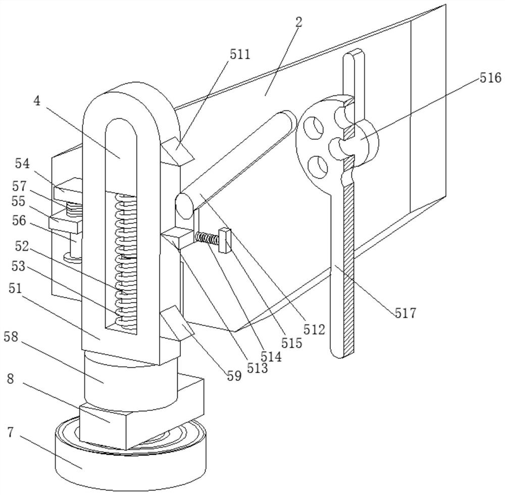
[0037] A fully automatic metal forging forming method, such as Figure 1-Figure 7 As shown, the box body 1 is included, and the front part of the box body 1 is welded with a mounting plate 2 and a support box 3 respectively, and the mounting plate 2 is located above the support box 3, and the front part of the mounting plate 2 is welded with a limit block 4. The surface of the block 4 is provided with a forging mechanism 5, the right side of the mounting plate 2 is provided with a transmission mechanism 6, the top of the support box 3 is connected with a placement plate 7 by bolts, and the top of the placement plate 7 is provided with a clamping mechanism 8.

[0038] In this embodiment, the forging mechanism 5 includes a slider 51, the inner wall of the slider 51 is welded with a telescopic column 52, and the surface of the telescopic column 52 is sleeved with a support spring 53, and the left side of the slider 51 is welded with a stopper 54. The front part of the plate 2 is we...

Embodiment 2

[0044] Such as Figure 7-Figure 9 As shown, the inner wall of the No. 1 chuck 661 is slidingly connected to the surface of the rotating shaft 67, and the front end of the contraction spring 662 is welded and fixed to the rear end of the limit plate 663. The contraction spring 662 can pull the No. 1 card after the inclined plate 664 moves down. Disk 661 resets, and then realizes that No. 1 chuck 661 can be separated from No. 2 chuck 665, so that rotating shaft 67 can move intermittently, so that the steel will not rotate during forging, preventing it from interfering with hammer head 58, causing Damage to the unit increases maintenance costs and reduces availability.

[0045] It is worth noting that the clamping mechanism 8 includes a mounting block 81, the inner wall of the mounting block 81 is rotatably connected with two clamping blocks 82, and an oil cylinder 83 is movably connected between the two clamping blocks 82, and the contact between the two clamping blocks 82 Stee...


PUM


Abstract

The invention relates to the technical field of forging forming, and discloses a full-automatic metal forging forming method. The full-automatic metal forging forming method comprises the steps that:a steel block is placed between two clamping blocks; an oil cylinder contracts to drive the two clamping blocks to clamp the steel block; furthermore, the steel block is placed on a placing plate; a motor is started; the motor drives a first gear to rotate; the first gear drives a second gear to rotate; the second gear drives a first belt wheel to rotate; the first belt wheel drives a short pokingplate to rotate; the short poking plate drives a long poking plate to rotate; the short poking plate drives a rotating plate to rotate; a sliding block downwards forges the steel block; after the first forging is completed, the long poking plate continues to rotate to drive the sliding block to move upwards and reset again; a rack drives a fourth gear to rotate; the fourth gear drives the steel block to rotate through the clamping blocks; when the sliding block falls down again, the steel block automatically turns over once; and the sliding block forges the steel block again. Steel can be automatically clamped and overturned while forging is carried out, so that manual overturning by workers is not needed, and the labour intensity of the workers is reduced.

Description

technical field [0001] The invention relates to the technical field of forging forming, in particular to a fully automatic metal forging forming method. Background technique [0002] Forging is a processing method that uses forging machinery to apply pressure to metal blanks to cause plastic deformation to obtain forgings with certain mechanical properties, certain shapes and sizes. One of the two major components of forging (forging and stamping), through forging It can eliminate defects such as as-cast looseness produced in the metal smelting process, optimize the microstructure, and at the same time, due to the preservation of complete metal flow lines, the mechanical properties of forgings are generally better than castings of the same material. [0003] At present, some smaller steel products are mostly turned over manually by workers, and in some cases of high temperature forging, manual turning will also cause a certain degree of difficulty in the forging of steel mat...

Claims


Application Information

Patent Timeline
IPC IPC(8): B21J7/06B21J7/42B21J9/06B21J9/18B21J13/10B21J13/12
CPCB21J7/06B21J7/42B21J9/06B21J9/18B21J13/10B21J13/12
Inventor 不公告发明人
Owner 谢娟
Why Eureka
Try Eureka