Assembly method of combined cartridge receiver
An assembly method and combined technology, applied in the direction of offensive equipment, weapon accessories, etc., can solve the problems of difficulty in ensuring the mutual position and size, complex manufacturing process of the casing, and high requirements for mutual position accuracy, and achieve the effect of improving accuracy and reliability
- Summary
- Abstract
- Description
- Claims
- Application Information
AI Technical Summary
Problems solved by technology
Method used
Image
Examples
Embodiment 1
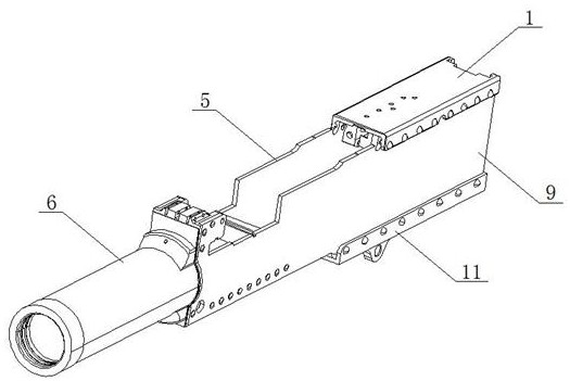
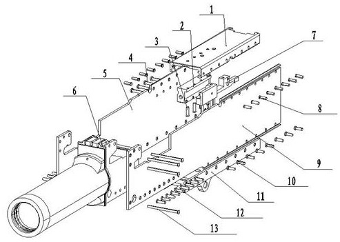
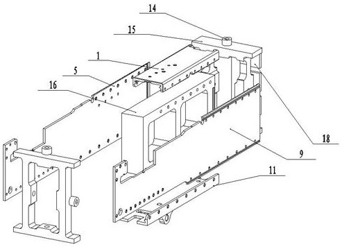
[0040] This embodiment discloses a method for assembling a combined casing. Figure 1-Figure 13 As shown, the assembly method specifically includes the following steps:
[0041] Step 1. First, place the left side plate 9 and the right side plate 5 of the receiver on both sides of the first positioning block 16, and engage the gun tail slots on the left side plate 9 and the right side plate 5 of the receiver respectively. Insert it into the positioning boss of the first positioning block 16, and then cover the casing upper cover 1 on the top of the left side plate 9 and the right side plate 5 of the casing in turn, and cover the left side plate 9 and the right side of the casing The lower part of the plate 5 is covered with the casing lower seat 11, so that the casing left side plate 9, the casing right side plate 5, the casing upper cover 1 and the casing lower seat 11 form a whole assembly, and then respectively cover the casing on the top of the assembly. Insert two positio...
Embodiment 2
[0053] This embodiment discloses a method for assembling a combined casing. Figure 1-Figure 13 As shown, on the basis of Embodiment 1, the casing upper cover 1, the casing lower seat 11, the casing left side plate 5, the casing right side plate 9, the buffer seat 2 and the lever seat 7 are all provided with preset Leave holes. During the assembly and processing of the casing, it is only necessary to drill the reserved holes of each component to the diameter of the rivet, so that the rivet can pass through smoothly, but the displacement between each component is very small.
[0054] Further, a slot is provided on the inner side of the upper cover 1 of the casing, and a boss adapted to the slot is provided on the buffer seat 2, and the boss is axially fixed in the slot.
[0055] Further, when the step eight is assembled, the second positioning block 26 is put into the assembly from the rear of the assembly, and the positioning groove on the second positioning block is just ali...
PUM
 Abstract
Description
Claims
Application Information
 - R&D
- Intellectual Property
- Life Sciences
- Materials
- Tech Scout
- Unparalleled Data Quality
- Higher Quality Content
- 60% Fewer Hallucinations
Browse by: Latest US Patents, China's latest patents, Technical Efficacy Thesaurus, Application Domain, Technology Topic, Popular Technical Reports.
© 2025 PatSnap. All rights reserved.Legal|Privacy policy|Modern Slavery Act Transparency Statement|Sitemap|About US| Contact US: help@patsnap.com


