
Chemical mechanical planarization tool

A chemical mechanical and flattening technology, which is applied in the direction of grinding machine tool parts, manufacturing tools, scientific instruments, etc., can solve problems such as uneven shape and difficulties

Active Publication Date: 2021-03-12
TAIWAN SEMICON MFG CO LTD
View PDF12 Cites 2 Cited by
  • Summary
  • Abstract
  • Description
  • Claims
  • Application Information

AI Technical Summary

Problems solved by technology

For example, forming metal features in a substrate or in a metal layer can lead to uneven topography
Such uneven topography may cause difficulties in forming subsequent layers

Method used


Image

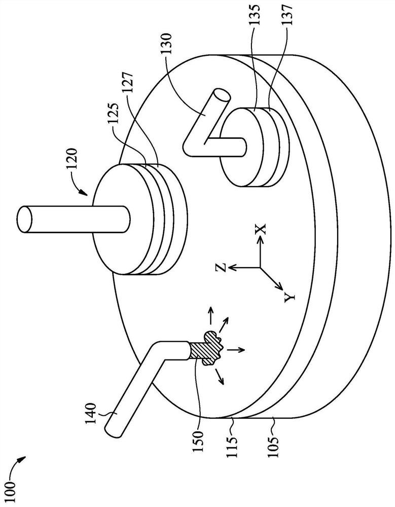
  • Chemical mechanical planarization tool
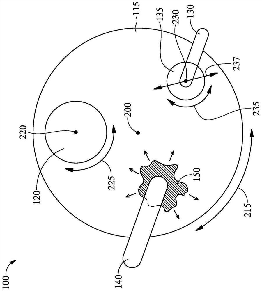
  • Chemical mechanical planarization tool
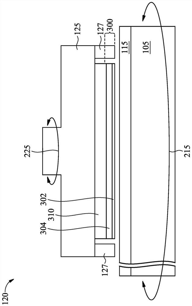
  • Chemical mechanical planarization tool

Examples


Embodiment Construction

[0047] The following disclosure provides many different embodiments, or examples, for implementing different features of the disclosure. Specific examples of components and arrangements are described below to simplify the present disclosure. Of course, the examples are for illustration only and are not intended to be limiting. For example, if the specification states that the first feature is formed on the second feature, it means that the above-mentioned first feature and the above-mentioned second feature may include embodiments in which the above-mentioned first feature and the above-mentioned second feature are in direct contact, and may also include an embodiment in which additional features are formed on the above-mentioned first feature and the above-mentioned second feature. Between the above-mentioned second features, the above-mentioned first feature and the second feature may not be in direct contact with each other. Additionally, in various instances, the present ...


PUM


Abstract

A method of operating a chemical mechanical planarization (CMP) tool includes attaching a polishing pad to a first surface of a platen of the CMP tool using a glue; removing the polishing pad from theplaten, wherein after removing the polishing pad, residue portions of the glue remain on the first surface of the platen; identifying locations of the residue portions of the glue on the first surface of the platen using a fluorescent material; and removing the residue portions of the glue from the first surface of the platen.

Description

technical field [0001] Some embodiments of the present disclosure relate to chemical mechanical polishing / chemical mechanical planarization. Background technique [0002] Semiconductor devices generally include active components, such as transistors, formed on a substrate. Any number of interconnection layers may be formed above the substrate to connect active components to each other or to external devices. The interconnect layers are typically made of low-k dielectric materials including metal trenches / vias. [0003] After the layers of the device are formed, a planarization process may be performed to planarize the layers to facilitate the formation of subsequent layers. For example, forming metal features in a substrate or in a metal layer can result in an uneven topography. Such uneven topography may cause difficulties in forming subsequent layers. For example, uneven topography can interfere with photolithography processes, which are commonly used to form various f...

Claims


Application Information

Patent Timeline
Patent Type & Authority Applications(China)
IPC IPC(8): B24B37/04B24B37/10B24B37/005B24B53/013
CPCB24B37/042B24B37/10B24B37/005B24B53/013B24B37/12B24B53/017B24B49/12B24B37/20G01N2021/6439G01N21/94G01N21/6456
Inventor 陈东楷王上瑜潘婉君魏民忠黄惠琪陈科维
Owner TAIWAN SEMICON MFG CO LTD
Learn More