
A four-wheel drive system for an all-terrain vehicle

A transmission system and technology for all-terrain vehicles, applied in the field of all-terrain vehicles, can solve problems such as affecting vehicle stability, unsuitable layout, and harsh driving conditions, so as to improve transmission efficiency and dynamic response speed, improve vehicle stability, Compact and convenient effect

Active Publication Date: 2022-07-05
XIAMEN UNIV OF TECH
View PDF0 Cites 0 Cited by
  • Summary
  • Abstract
  • Description
  • Claims
  • Application Information

AI Technical Summary

Problems solved by technology

[0003] First, for an all-terrain vehicle using a differential, when passing a bumpy road, because one wheel is off the ground, the differential will transfer power to the off-ground wheel, resulting in power loss;
[0004] Second, the differential is large in size, takes up a large space, and has a large mass, which is not conducive to the layout of the front and rear axles and other components. For complex road conditions, a large rear axle load will affect the stability of the vehicle and increase power. consumption, and the transmission efficiency becomes lower;
[0005] Third, in order to ensure that the front axle wheels can roll freely without dragging when the vehicle is cornering, most of the four-wheel drive transmission systems used in passenger cars use complex Torsen differentials or electronic differentials. The ATV has a small front axle space, and the circuit structure of the whole vehicle is also relatively simple. At the same time, the driving conditions are harsh, so it is not suitable for the arrangement of a Torsen differential or an electronic differential with a complex structure.

Method used


Image

  • A four-wheel drive system for an all-terrain vehicle
  • A four-wheel drive system for an all-terrain vehicle
  • A four-wheel drive system for an all-terrain vehicle

Examples


Embodiment Construction

[0034] In order to further explain the technical solutions of the present invention, the present invention will be described in detail below through specific embodiments.

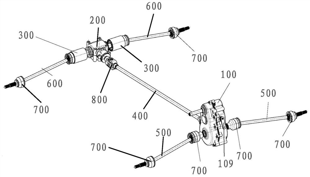
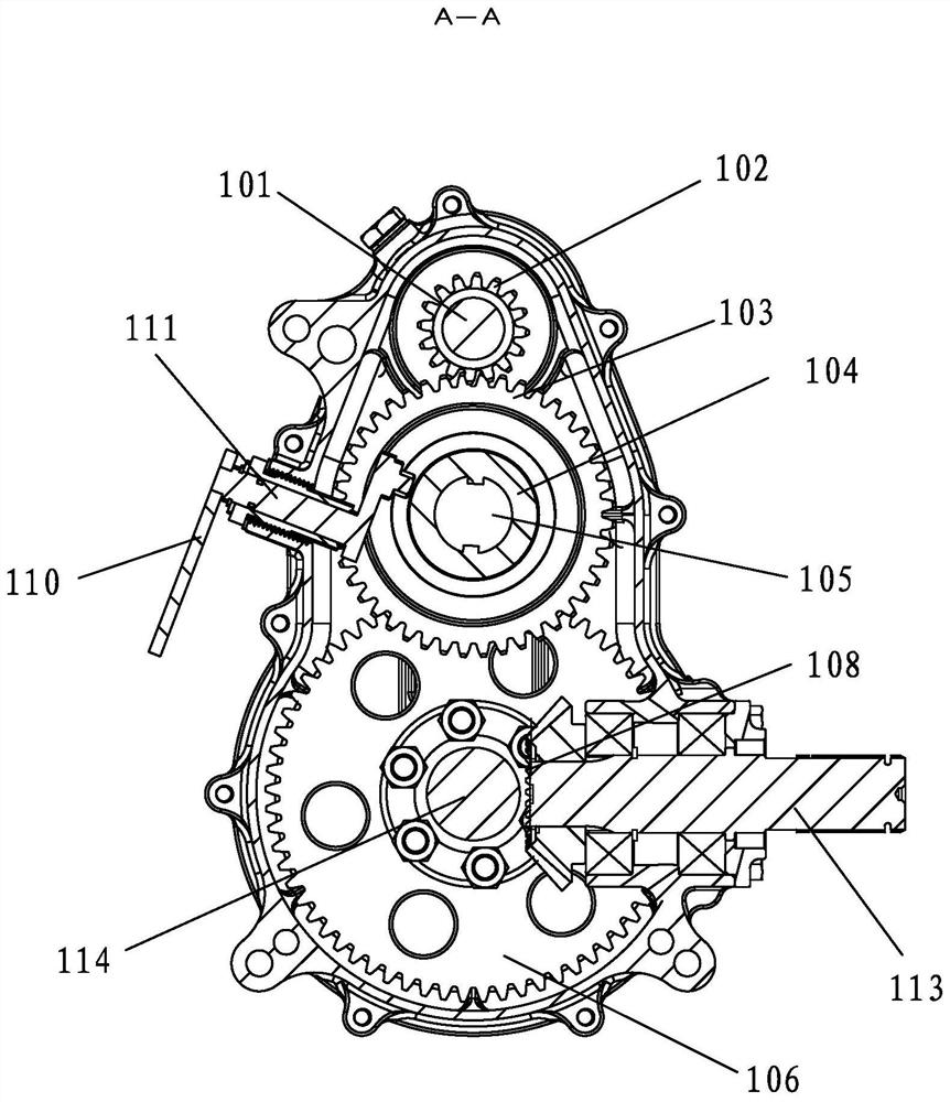
[0035] like Figure 1-8 As shown, this case provides a four-wheel drive transmission system for an all-terrain vehicle, which includes a rear axle transfer reducer 100, a front axle reducer 200, a coupling 300, an intermediate transmission shaft 400, two rear axle shafts 500 and two front half shafts 600, the front half shaft 600 is connected to the front wheel of the car through the constant velocity joint 700, and the rear half shaft 500 is connected to the rear wheel of the car through the constant velocity joint 700. The rear axle transfer reducer 100 includes a first input shaft 112 connected with the engine, a middle output shaft 113 connected with the first input shaft 112 in a driving manner, and a cross universal joint is passed between the first input shaft 112 and the middle output shaft 113 . T...


PUM


Abstract

The invention discloses a four-wheel drive transmission system for an all-terrain vehicle, which comprises a rear axle transfer reducer, a front axle reducer, a coupling, an intermediate transmission shaft, two rear half shafts and two front half shafts, The rear axle transfer reducer includes a first input shaft connected with the engine, a middle output shaft connected with the first input shaft, a first side output shaft connected with the middle output shaft, and both ends of the first side output shaft. The two rear axle shafts are respectively connected, the front axle reducer includes a second input shaft connected with the intermediate transmission shaft and a second side output shaft connected with the second input shaft in a driving manner, and the coupling includes a first housing , One-way bearing and constant-velocity universal joint respectively connected to both ends of the first housing, the outer ring of the one-way bearing is drive-connected with the first housing and the inner ring is drive-connected with the output shaft on the second side, the constant-velocity universal joint The section is connected with the front half shaft. This case aims at improving the transmission efficiency, dynamic response and reducing power consumption of the transmission system for complex road conditions.

Description

technical field [0001] The invention relates to the technical field of all-terrain vehicles, in particular to a four-wheel drive transmission system for all-terrain vehicles. Background technique [0002] All-terrain vehicle is a vehicle designed for complex road conditions. It mainly drives on roads such as cannonball craters, double humps, sand, gravel, etc., and the maximum speed is low, about 60-70 kilometers per hour, so , ATVs have higher requirements for transmission efficiency, dynamic response and power consumption at low speeds. The existing transmission systems of ATVs include front reducer, rear reducer, transfer case, differential, and half shafts. It is composed of other components. The differential is connected to the half shafts through the three-ball pin type constant velocity universal joint. Although it can adjust the speed difference between the two half shafts, it also brings at least the following defects: [0003] First, for an all-terrain vehicle usi...

Claims


Application Information

Patent Timeline
Patent Type & Authority Patents(China)
IPC IPC(8): B60K17/344B60K17/22B60B35/12
CPCB60K17/344B60K17/22B60B35/128Y02T10/62
Inventor 洪汉池李宇星王远森张灿育陈云
Owner XIAMEN UNIV OF TECH
Learn More