Eureka AIR delivers breakthrough ideas for toughest innovation challenges, trusted by R&D personnel around the world.

Unmanned helicopter electrical system design method

An unmanned helicopter and electrical system technology, applied in the field of unmanned helicopter electrical system design, can solve problems such as single function, imperfect electrical system architecture, and inconvenient use

Pending Publication Date: 2021-03-12
AEROSPACE SHENZHOU AIRCRAFT
View PDF8 Cites 0 Cited by
  • Summary
  • Abstract
  • Description
  • Claims
  • Application Information

AI Technical Summary

Problems solved by technology

[0002] With the development of adaptive control technology, the adaptive flight of unmanned helicopters has been widely studied all over the world. Unmanned helicopters have many advantages that unmanned fixed-wing aircraft do not have, and have unique flight performance and use value. The unmanned helicopter flight control system is a typical nonlinear, strong coupling, multi-variable, and multi-drive system. Each variable has an impact on the flight attitude, flight direction, flight height, and flight speed of the unmanned helicopter. The stability boundary of the system changes greatly with the change of flight conditions. At present, small unmanned helicopters have been more and more widely used, and various autonomous flight control systems have also appeared, but the electrical system structure is not perfect, and the use is not perfect. Convenience, single function

Method used


Image

  • Unmanned helicopter electrical system design method
  • Unmanned helicopter electrical system design method
  • Unmanned helicopter electrical system design method

Examples


Embodiment approach

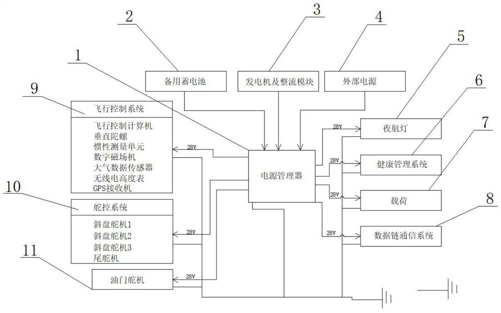
[0023] As a preferred embodiment of the present invention, the power supply includes a power manager 1, a backup battery 2, a generator and a rectifier module 3 and an external power supply 4, the generator and rectifier module 3 are the main power supply, and the backup battery 2 is the on-board lithium battery.

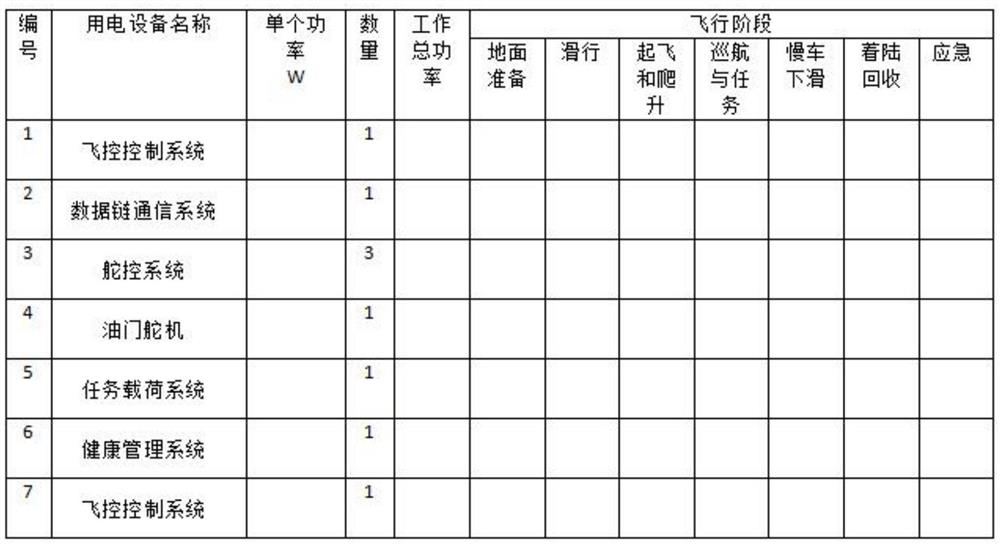
[0024] Power capacity analysis table - power supply load table is as follows:

[0025]

[0026] Table II

[0027] Power capacity analysis - load working time statistical table is as follows:

[0028]

[0029] Table three

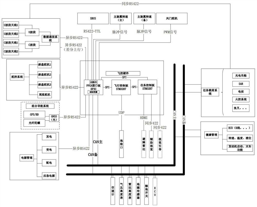
[0030] As a preferred embodiment of the present invention, the flight control system 9 includes a flight control computer, a vertical gyroscope, an inertial measurement unit, a digital magnetic field machine, an air data sensor, a radio altimeter and a GPS receiver.

[0031] As a preferred embodiment of the present invention, the flight control computer is the core of information processing and exchange of the whole machine, the GPS recei...


PUM


Abstract

The invention provides an unmanned helicopter electrical system design method in which a power manager, a standby storage battery, a generator, a rectification module, an external power supply, a night navigation lamp, a health management system, a load, a data link communication system, a flight control system, a rudder control system and an accelerator steering engine are arranged. The unmannedhelicopter electrical system design method is a universal unmanned helicopter electrical system design method, electrical system design can be carried out according to the overall requirements, the system should work reliably in any flight state, and the average fault interval time should meet the overall requirements of an airplane.

Description

technical field [0001] The invention relates to the field of unmanned helicopter equipment, in particular to a design method for an unmanned helicopter electrical system. Background technique [0002] With the development of adaptive control technology, the adaptive flight of unmanned helicopters has been widely studied all over the world. Unmanned helicopters have many advantages that unmanned fixed-wing aircraft do not have, and have unique flight performance and use value. The unmanned helicopter flight control system is a typical nonlinear, strong coupling, multi-variable, and multi-drive system. Each variable has an impact on the flight attitude, flight direction, flight height, and flight speed of the unmanned helicopter. The stability boundary of the system changes greatly with the change of flight conditions. At present, small unmanned helicopters have been more and more widely used, and various autonomous flight control systems have also appeared, but the electrical...

Claims


Application Information

Patent Timeline
IPC IPC(8): B64C27/04B64D41/00B64D45/00B64C13/50B64F5/00
CPCB64C27/04B64D41/00B64D45/00B64C13/50B64F5/00B64D2045/0085
Inventor 商智凯刘涛李广磊
Owner AEROSPACE SHENZHOU AIRCRAFT
Why Eureka
Eureka Blog
Learn More