Magnetic levitation track assembly for textile machine and textile machine
A textile machine and magnetic levitation technology, which is applied in the textile field, can solve problems such as inconvenience, transportation efficiency cannot be improved, and assembly line cannot run normally, so as to achieve the effect of improving fluency, fluency and stability
- Summary
- Abstract
- Description
- Claims
- Application Information
AI Technical Summary
Problems solved by technology
Method used
Image

Examples
Embodiment Construction
[0025] The following will clearly and completely describe the technical solutions in the embodiments of the present invention with reference to the accompanying drawings in the embodiments of the present invention. Obviously, the described embodiments are only some, not all, embodiments of the present invention. Based on the embodiments of the present invention, all other embodiments obtained by persons of ordinary skill in the art without making creative efforts belong to the protection scope of the present invention.
[0026] Refer to the attached Figure 1-7 , an embodiment provided by the present invention:
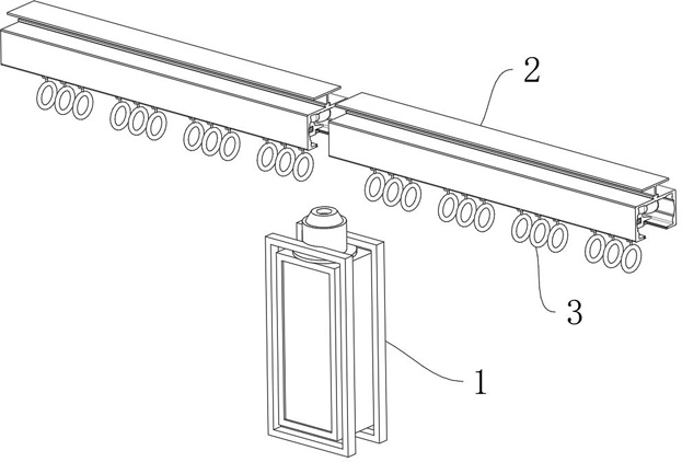
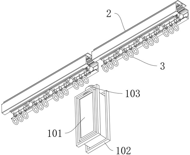
[0027]A magnetic levitation track assembly for a textile machine and a textile machine, including a textile equipment 1, wherein the textile equipment 1 is a HTMDD15-100 series weaving textile equipment, and the top of the textile equipment 1 is fixedly equipped with a plurality of cantilever-type corresponding rails Mechanism 2, multiple cantilever-type correspondin...
PUM
 Abstract
Description
Claims
Application Information
PatSnap Eureka turns technology decisions into work you can execute. Powered by our Innovation Knowledge Graph, it runs expert workflows across engineering, life sciences, materials and intellectual property. Get your review-ready output in minutes.


