High-speed maglev bridge large-displacement telescopic device

A telescoping device and large displacement technology, applied in bridges, bridge parts, bridge construction, etc., can solve the problems of uneven gap size, large structure volume, poor structural durability, etc., and achieve large longitudinal displacement expansion and structural stress clear, structurally small effect

Active Publication Date: 2021-03-12
CHINA RAILWAY MAGLEV TRANSPORTATION INVESTMENT CONSTR CO LTD +1
View PDF11 Cites 5 Cited by
  • Summary
  • Abstract
  • Description
  • Claims
  • Application Information

AI Technical Summary

Problems solved by technology

[0007] 1. It is only applicable to the composite beam scheme (that is, the simply supported track beam scheme on the bridge), and not applicable to the pure track beam scheme or the bridge scheme with track slabs laid on the bridge;
[0008] 2. The structural volume is too large, and the length of each track beam is at least 4 meters. If the telescopic device is to adapt to a telescopic amount of more than 1000mm, the length of the telescopic device will reach more than 40 meters;
[0009] 3. There are many movable supports, the installation accuracy is not easy to control, and the horizontal deformation of the uneven size of the gap is prone to occur when the vehicle passes
[0012] 1. It is only applicable to the composite beam scheme (that is, the simply supported track beam scheme on the bridge), and not applicable to the pure track beam scheme or the bridge scheme with track slabs laid on the bridge;
[0013] 2. The structural volume is too large, and the length of each track beam is at least 4 meters. If the telescopic device is to adapt to a telescopic amount of more than 1000mm, the length of the telescopic device will reach more than 40 meters;
[0014] 3. There are defects in the struct

Method used


Image

  • High-speed maglev bridge large-displacement telescopic device
  • High-speed maglev bridge large-displacement telescopic device
  • High-speed maglev bridge large-displacement telescopic device

Examples


Embodiment Construction

[0094] In order to make the object, technical solution and advantages of the present invention clearer, the present invention will be further described in detail below in conjunction with the accompanying drawings and embodiments. It should be understood that the specific embodiments described here are only used to explain the present invention, not to limit the present invention. In addition, the technical features involved in the various embodiments of the present invention described below can be combined with each other as long as they do not constitute a conflict with each other. The present invention will be further described in detail below in combination with specific embodiments.

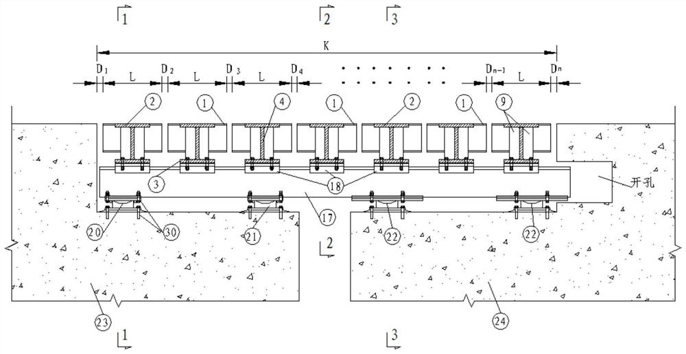
[0095] Such as figure 1 As shown, grooves are respectively provided on the upper edge of the beam end where the bridge beam structure 23 on the fixed side connects with the bridge beam structure 24 on the movable side for installing the high-speed maglev bridge large-displacement telescopic...


PUM


Abstract

The invention discloses a high-speed maglev bridge large-displacement telescopic device, which is characterized in that a unique long stator track unit module system is constructed and comprises a cross beam unit and a long stator track assembly, so that the segmentation of a stator iron core and the continuous scalability of a long stator coil are realized; the device can adapt to suspension, guiding, traction driving and running of emergency running wheels at the same time, several brand-new sub-systems such as a longitudinal beam system, a fastener system, a longitudinal limiting system, aconnecting rod system and a spring system are further designed, and large-displacement stretching and retracting of high-speed maglev traffic are achieved. The device is not only suitable for a superposed beam scheme, but also suitable for a pure track beam scheme or a bridge scheme of paving track plates on a bridge; the structural body is small in size, clear in structural stress and good in durability; through the synergistic effect of a connecting rod system and a spring system, the longitudinal gaps between any two long stator track unit module systems can be equal in any telescopic state.

Description

technical field [0001] The invention belongs to the field of high-speed maglev bridges, in particular to a large-displacement telescopic device for high-speed maglev bridges. Background technique [0002] The charged levitation electromagnet on the levitation frame of the high-speed maglev train and the long stator core on the track attract each other to provide the levitation force for the train, attract the train upwards, and ensure a stable levitation gap by controlling the levitation excitation current. The suspension gap between the electromagnet and the track is generally controlled at 8mm-12mm. [0003] The charged guiding electromagnet on the suspension frame interacts with the guiding plate on the side of the track to provide guiding force to keep a certain lateral distance between the car body and the track to realize non-contact guiding in the horizontal direction. [0004] The drive of the high-speed maglev train adopts the non-vehicle power device - the long st...

Claims


Application Information

Patent Timeline
IPC IPC(8): E01D19/06E01B25/30
CPCE01D19/06E01D19/065E01B25/30E01B25/305
Inventor 龚俊虎刘武斌冯亮鄢巨平张家炳翟婉明赵春发
Owner CHINA RAILWAY MAGLEV TRANSPORTATION INVESTMENT CONSTR CO LTD
Why Eureka
Try Eureka