
Underground cavern consolidation grouting method under high external water pressure dynamic water condition

A technology for consolidating grouting and underground caverns, applied in infrastructure engineering, protection devices, buildings, etc., can solve problems such as water gushing, and achieve the effect of reasonable and feasible technology, cost saving, and quality control.

Active Publication Date: 2021-03-12
CHINA HYDROELECTRIC ENGINEERING CONSULTING GROUP CHENGDU RESEARCH HYDROELECTRIC INVESTIGATION DESIGN AND INSTITUTE
View PDF6 Cites 0 Cited by
  • Summary
  • Abstract
  • Description
  • Claims
  • Application Information

AI Technical Summary

Problems solved by technology

[0007] The invention provides a consolidation grouting method for underground caverns, which solves the problem of a large amount of water gushing from cracks in surrounding rocks in underground caverns under high external pressure conditions, avoids the influence of dynamic water on the consolidation grouting construction, and ensures the construction quality of consolidation grouting

Method used


Image

  • Underground cavern consolidation grouting method under high external water pressure dynamic water condition
  • Underground cavern consolidation grouting method under high external water pressure dynamic water condition
  • Underground cavern consolidation grouting method under high external water pressure dynamic water condition

Examples


Embodiment Construction

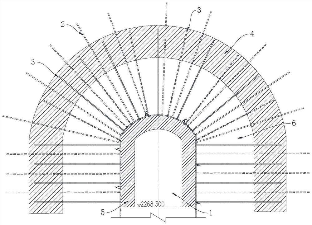
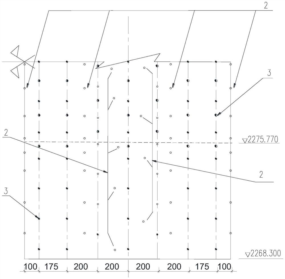
[0053] The present invention will be further described below by taking the consolidation grouting of the underground sluice chamber of the reconstruction vent tunnel of the Duonuo Hydropower Station in Jiuzhaigou County, Sichuan Province as an example. Under the condition of high external water pressure and dynamic water, the consolidation grouting method of underground caverns adopts the strategy of orderly drainage of deep drainage holes and peripheral sealing and blocking, supplemented by rock surface sealing, for seepage and gushing water. The basic conditions for lining concrete pouring and subsequent consolidation grouting construction, refer to figure 1 and figure 2 , including the following steps:

[0054] S1. Drill deep drainage holes on the rock wall of the underground cavern to conduct concentrated drainage of seepage and gushing water.

[0055] Due to the well-developed fissures in the surrounding rock of the underground sluice chamber, seepage gushing water eme...


PUM


Abstract

The invention discloses an underground cavern consolidation grouting method under a high external water pressure dynamic water condition, and relates to the field of underground engineering. The problem that a large amount of water bursts into surrounding rock cracks of an underground cavern under the high external pressure condition is solved, the influence of the dynamic water effect on consolidation grouting construction is avoided, and the consolidation grouting construction quality is guaranteed. According to the technical scheme, the underground cavern consolidation grouting method underthe high external water pressure dynamic water condition comprises the steps that firstly, deep drainage holes are drilled in a rock body of the underground cavern, and leakage gushing water is guided and drained in a centralized mode; then water plugging holes are drilled in the rock body of the underground cavern, and water plugging grouting is carried out on water blocking curtain hole sections of the water plugging holes to form a water blocking curtain; the deep drainage holes are blocked; a rock face is sealed, and lining concrete is constructed on the rock face of the underground cavern to form a consolidated grouting cover weight body; and finally, consolidation grouting is carried out on the area between the lining concrete and the water blocking curtain. The underground cavern consolidation grouting method under the high external water pressure dynamic water condition is suitable for underground cavern consolidation grouting under the high external water pressure dynamic water condition.

Description

technical field [0001] The invention relates to the field of underground engineering, in particular to a method for consolidation and grouting of underground caverns under the condition of high external water pressure and dynamic water. Background technique [0002] In the case of sufficient sources of groundwater supply and continuous high groundwater level, the rock cracks in the excavated underground caverns often have large and continuous water gushing. Under such conditions, the consolidation grouting of the rock mass around the underground caverns Construction, after the grouting and drilling is completed, the grouting hole actually becomes a drainage hole, and the water in the hole will not stop. Due to the influence of internal flow water, the grouting quality is difficult to meet the specified requirements. At present, my country's current "Technical Specifications for Cement Grouting Construction of Hydraulic Structures" (DL / T 5148-2012) does not cover the specifi...

Claims


Application Information

Patent Timeline
Patent Type & Authority Applications(China)
IPC IPC(8): E02D19/06E02D19/18E02D31/00E02D15/00
CPCE02D19/06E02D19/18E02D31/00E02D15/00
Inventor 颉建军李建彬周荣刘宗健唐朝阳胡帅
Owner CHINA HYDROELECTRIC ENGINEERING CONSULTING GROUP CHENGDU RESEARCH HYDROELECTRIC INVESTIGATION DESIGN AND INSTITUTE
Learn More