Wide viscosity type liquid turbine flow sensor

A technology of flow sensor and liquid turbine, which is applied in the direction of volume/mass flow generated by mechanical effects, and by detecting the dynamic effects of fluid flow, etc., which can solve problems such as large errors, and achieve the effect of improving instrument performance, stabilizing performance, and maintaining performance

Pending Publication Date: 2021-03-12
HEBEI UNIVERSITY
View PDF0 Cites 0 Cited by
  • Summary
  • Abstract
  • Description
  • Claims
  • Application Information

AI Technical Summary

Problems solved by technology

[0005] The purpose of the present invention is to provide a wide-viscosity liquid turbine flow sensor to solve the

Method used


Image

  • Wide viscosity type liquid turbine flow sensor
  • Wide viscosity type liquid turbine flow sensor
  • Wide viscosity type liquid turbine flow sensor

Examples


Embodiment Construction

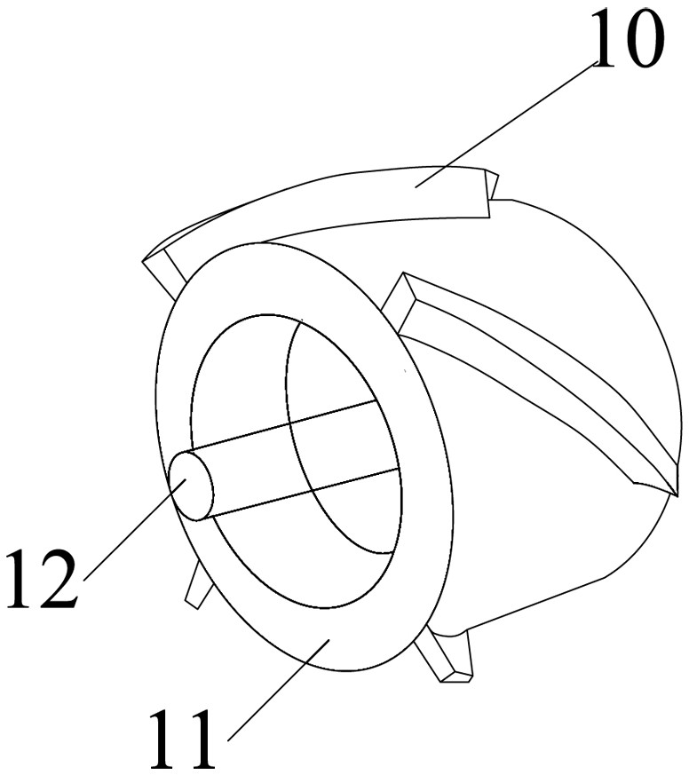
[0015] The liquid turbine flow sensor of the present invention is mainly for improvements to the impeller portion. Such as figure 1 As shown, the axle shaft 12 is provided on the axial center line of the impeller 11, and the outer end of the wheel shaft 12 projects the end face of the impeller to support the impeller in the housing of the turbine flow sensor. The four blade 10 are evenly distributed on the wheel surface of the impeller 11, and each of the blade 10 is fixedly attached to the wheel surface of the impeller 11. The blade distribution form on the impeller 11 is that the end of the front blade is inserted in the impeller axis of the rear blade. That is, the two adjacent blades 10 have no slit in the axial direction of the impeller 11, there is no overlap, and a closed loop structure is formed. Further, the ratio of the diameter of the impeller 11 and the housing of the mounting impeller is 0.8: 1.

[0016] The outer diameter of the housing of the liquid turbine flow se...


PUM


Abstract

The invention provides a wide viscosity type liquid turbine flow sensor which comprises a shell and an impeller, a plurality of blades are evenly distributed on a hub of the impeller, the blades are spirally arranged on the hub of the impeller, and the blades on the impeller are distributed in the axial direction of the impeller as follows: the tail end of the previous blade is connected with thestarting end of the next blade. in terms of the axial direction of the impeller, the joint part of two adjacent blades has no gap and no overlap, and a closed circular ring is just formed. The lengthof the impeller is designed according to the speed profile of the maximum viscosity point, the blade compactness of the impeller is increased through the length design of the impeller, the leakage amount, increased along with the increase of viscosity, between blades is reduced, then the driving torque of fluid to the impeller is increased, so that the stable performance can be kept when wide-viscosity liquid is measured. Therefore, the performance of the turbine flow sensor is improved.

Description

Technical field [0001] The present invention relates to a flow measuring device, specifically a wide viscous type liquid turbine flow sensor. Background technique [0002] The turbine flow sensor is a kind of flow measuring instrument having a higher measurement accuracy, due to wide range, repetitive, widely used in natural gas and oil trade measurements. [0003] The working principle of the turbine flow sensor flows through the voids between the sensor housing and the impeller. Since the blades on the impeller have a certain angle, the fluid acts on the blade, providing a rotational momentum, rotating for the impeller After overcoming the friction torque and fluid resistance, the impeller reaches the torque balance to stabilize the rotational speed of the impeller. Under certain conditions, the rotational speed of the impeller is proportional to the flow rate of the fluid. Since the blade has magnetic properties, it is in a magnetic field of the signal detector (consisting of ...

Claims


Application Information

Patent Timeline
IPC IPC(8): G01F1/28
CPCG01F1/28
Inventor 郭素娜杨子航赵宁王帆方立德
Owner HEBEI UNIVERSITY
Why Eureka
Try Eureka