Supercharge Your Innovation With Domain-Expert AI Agents!

Laser radar and camera time synchronization system and method

A technology of time synchronization system and laser radar, which is applied in the field of rail transit, can solve problems such as performance problems, low sampling frequency, and poor quality of data fusion, and achieve the effect of improving the quality of data fusion

Pending Publication Date: 2021-03-12
浙江众合科技股份有限公司
View PDF0 Cites 3 Cited by
  • Summary
  • Abstract
  • Description
  • Claims
  • Application Information

AI Technical Summary

Problems solved by technology

However, there is no time synchronization (the synchronization here includes data sampling frequency and phase synchronization) interface between traditional sensors, resulting in poor quality or even failure of the final data fusion
Especially when the sampling frequency is low and the moving speed of the detected target is fast, the performance problem caused by multi-sensor time synchronization is particularly obvious

Method used


Image

  • Laser radar and camera time synchronization system and method
  • Laser radar and camera time synchronization system and method

Examples


Embodiment 1

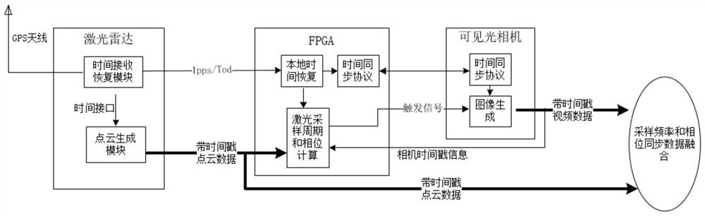
[0030] Such as figure 1 As shown, a lidar and camera time synchronization system, including:

[0031] Laser radar: the laser radar is provided with a time receiving recovery module and a point cloud generation module, and the time receiving recovery module receives the satellite timing signal, recovers the standard time, and outputs it to the point cloud generation module, and at the same time outputs it to the programmable logic device Standard time interface signal, the point cloud generation module generates and outputs time-stamped laser point cloud data to the programmable logic device according to the standard time;

[0032] Visible light camera: the visible light camera is equipped with a time synchronization protocol module 1 and an image generation module, the image generation module supports a trigger signal, and when there is an external trigger signal (such as a rising edge), the image acquisition and output are completed, and the image output is with have a times...

Embodiment 2

[0040] A kind of laser radar and camera time synchronization method, concrete implementation comprises the following steps:

[0041] 1. The lidar receives GPS signals, and the time receiving and recovery module locks the GPS time, and outputs it to the internal point cloud generation module, and at the same time outputs 1pps / Tod signal externally;

[0042] 2. The FPGA receives the 1pps / Tod signal, and the local time recovery module maintains a time counter inside the FPGA (which can be realized through a digital phase-locked loop), completing the time synchronization between the FPGA and the laser;

[0043] 3. The FPGA completes the time synchronization between the FPGA and the visible light camera through a time synchronization protocol module and the peer-to-peer time synchronization protocol module in the visible light camera;

[0044] Through steps 1, 2, and 3, the lidar, FPGA, and visible light camera have completed time synchronization.

[0045] 4. The lidar point cloud...


PUM


Abstract

The invention discloses a laser radar and camera time synchronization system and method. The system comprises laser radar which is provided with a time receiving recovery module and a point cloud generation module, wherein the time receiving recovery module receives a satellite time service signal, and recovers the standard time, and the point cloud generation module generates laser point cloud data with timestamps according to the standard time and outputs the laser point cloud data with the timestamps to the programmable logic device; a visible light camera which is provided with a time synchronization protocol module I and an image generation module, wherein the image generation module completes image acquisition and output according to the trigger signal, and image output has a timestamp; and a programmable logic device which is provided with a local time recovery module, a time synchronization protocol module II, a laser sampling period and a phase calculation module. Time synchronization of the laser radar, the programmable logic device and the visible light camera is realized, frequency and phase synchronization of the laser point cloud data and the image data is completed,and the data fusion quality is improved.

Description

technical field [0001] The invention relates to the technical field of rail transit, in particular to driverless sensor technology. Background technique [0002] In the field of unmanned driving, multi-sensor (typically laser and camera) data fusion is required. However, there is no time synchronization (the synchronization here includes data sampling frequency and phase synchronization) interface between traditional sensors, resulting in poor quality or even failure of the final data fusion. Especially when the sampling frequency is low and the moving speed of the detected target is fast, the performance problem caused by multi-sensor time synchronization is particularly obvious. Contents of the invention [0003] In view of the defects existing in the prior art, the technical problem to be solved by the present invention is to provide a laser radar and camera time synchronization system and method to realize the time synchronization of laser radar and camera and improve...

Claims


Application Information

Patent Timeline
IPC IPC(8): G01S17/86G01S7/48
CPCG01S17/86G01S7/48
Inventor 袁锦辉陈小波陶芸
Owner 浙江众合科技股份有限公司
Features
  • R&D
  • Intellectual Property
  • Life Sciences
  • Materials
  • Tech Scout
  • Unparalleled Data Quality
  • Higher Quality Content
  • 60% Fewer Hallucinations
Learn More