Railway locomotive part image edge enhancement method

A railway locomotive and image edge technology, applied in the field of image processing, can solve the problems of poor anti-noise and low robustness, and achieve the effect of strong robustness, good anti-interference and anti-noise ability

Inactive Publication Date: 2021-03-12
HARBIN KEJIA GENERAL MECHANICAL & ELECTRICAL CO LTD
View PDF8 Cites 0 Cited by
  • Summary
  • Abstract
  • Description
  • Claims
  • Application Information

AI Technical Summary

Problems solved by technology

[0007] The purpose of the present invention is to propose an image edge enhancement method for railway locomotive pa...

Method used


Image

  • Railway locomotive part image edge enhancement method
  • Railway locomotive part image edge enhancement method
  • Railway locomotive part image edge enhancement method

Examples


specific Embodiment approach 1

[0053] Specific implementation mode one: refer to Figure 11 Describe this embodiment in detail, a kind of railway locomotive component image edge enhancement method of this embodiment, comprises the following steps:

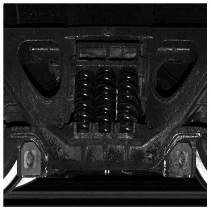
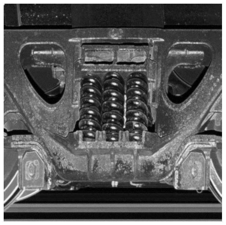
[0054] Step 1: Obtain the linear array image of the railway locomotive;

[0055] Step 2: intercepting locomotive component sub-images according to the linear image of railway locomotives;

[0056] Step 3: Preprocess the intercepted locomotive component subimages and convert them into three identical image matrices AHE 1 (x,y), AHE 2 (x,y) and AHE 3 (x, y);

[0057] Step 4: AHE the image matrix 1 (x, y) is converted into a spectral image by Fourier transform, and the spectral image is filtered by a Gaussian high-pass filter to obtain an image matrix H(u, v), and then the image matrix H(u, v) is passed through Fourier The leaf inverse transform is converted back to the space domain to obtain the image matrix I(x, y);

[0058] Step 5: AHE the image matrix 2...

specific Embodiment approach 2

[0072] Specific embodiment 2: This embodiment is a further description of specific embodiment 1. The difference between this embodiment and specific embodiment 1 is that the specific steps of preprocessing in step 3 are: first, carry out the process on the intercepted locomotive parts subgraph value filtering, and then perform adaptive histogram equalization processing on the locomotive parts subgraph after median filtering.

specific Embodiment approach 3

[0073] Embodiment 3: This embodiment is a further description of Embodiment 2. The difference between this embodiment and Embodiment 2 is that the median filter is expressed as:

[0074] Mdian(x, y) = median A {f(x,y)}

[0075] Among them, A is a window with a size of 3*3, and f(x,y) is an image matrix.

[0076] First, median filtering is performed on the obtained sub-image to eliminate the isolated noise points generated during the acquisition process of the line array camera. Median filter formula:

[0077] Mdian(x, y) = median A {f(x,y)}

[0078] Among them, A is a window with a size of 3*3, and {f(x,y)} is an image matrix.

[0079] Then, adaptive histogram equalization (AHE) is performed on the image. Since the image collected by the line scan camera will produce different light and dark effects with the different lumens of the area, but the pixel value transformation law between the edge area and the non-edge area is The same, therefore, in order to make the collect...


PUM


Abstract

The invention discloses a railway locomotive part image edge enhancement method, relates to the technical field of image processing, and aims to solve the problem that only edge information is enhanced and main body information is discarded in an existing edge enhancement method in the prior art. The method comprises the following steps: 1, obtaining an array image; 2, capturing a locomotive partsub-graph according to the linear array image; 3, preprocessing the captured locomotive part sub-images, and converting the preprocessed locomotive part sub-images into three same image matrixes; 4, converting one image matrix into a frequency spectrum image through Fourier transform, filtering the frequency spectrum image through a Gaussian high-pass filter to obtain an image matrix, and converting the image matrix back to a spatial domain through inverse Fourier transform to obtain an image matrix; 5, filtering the remaining two image matrixes through two different filters to obtain an imagematrix and an image matrix; and 6, normalizing the image matrix, multiplying the sum by the weight, and adding to obtain a single-channel image matrix.

Description

technical field [0001] The invention relates to the technical field of image processing, in particular to an image edge enhancement method for railway locomotive components. Background technique [0002] Existing edge enhancement methods include: Sobel operator edge detection, Canny operator edge detection, high-pass filter to extract contour information, double threshold method edge detection, and second-order differential edge detection. The above-mentioned algorithms belong to the category of classical image processing, and they are all implemented for the purpose of emphasizing the edge. That is to say, the above-mentioned algorithms take the edge information as the high gray value and the non-edge information as the second gray value in the processing results. presented. Although the above algorithm is robust to the extraction of edge information, it also has the following problems: [0003] 1. Although the edge information of the object in the image is highlighted, t...

Claims


Application Information

Patent Timeline
IPC IPC(8): G06T5/00G06T7/00G06T7/13
CPCG06T5/002G06T7/0004G06T7/13
Inventor 石玮
Owner HARBIN KEJIA GENERAL MECHANICAL & ELECTRICAL CO LTD
Why Eureka
Try Eureka