Control method for power exchange between main network and household optical storage system

A technology of power exchange and control method, applied in the field of electric energy storage, which can solve the threat of household load electricity reliability, increase the difficulty of power grid dispatching, rarely consider renewable energy and other issues, and achieve improved consumption capacity and energy exchange Small, reduced fluctuation effect

Pending Publication Date: 2021-03-12
NINGBO ELECTRIC POWER DESIGN INST
View PDF3 Cites 5 Cited by
  • Summary
  • Abstract
  • Description
  • Claims
  • Application Information

AI Technical Summary

Problems solved by technology

At present, most of the studies on the optimal control of household grid-connected photovoltaic power generation systems with energy storage start from the economic benefits of system operation, and seldom consider reducing household dependence on the grid and weakening the impact of grid-connected fluctuating renewable energy on the grid. impact, increasing the on-site integration of renewable energy as a major research objective
Moreover, the access of large-scale distributed photovoltaic power sources on the user side will have an impact on the power grid, increasing the difficulty of power grid dispatching
At the same time, household users with photovoltaic power generation will have a great dependence on the grid when they are connected to the grid. When the grid fails and the power is cut off, the reliability of household load power consumption will be threatened.

Method used


Image

  • Control method for power exchange between main network and household optical storage system
  • Control method for power exchange between main network and household optical storage system
  • Control method for power exchange between main network and household optical storage system

Examples


specific Embodiment 1

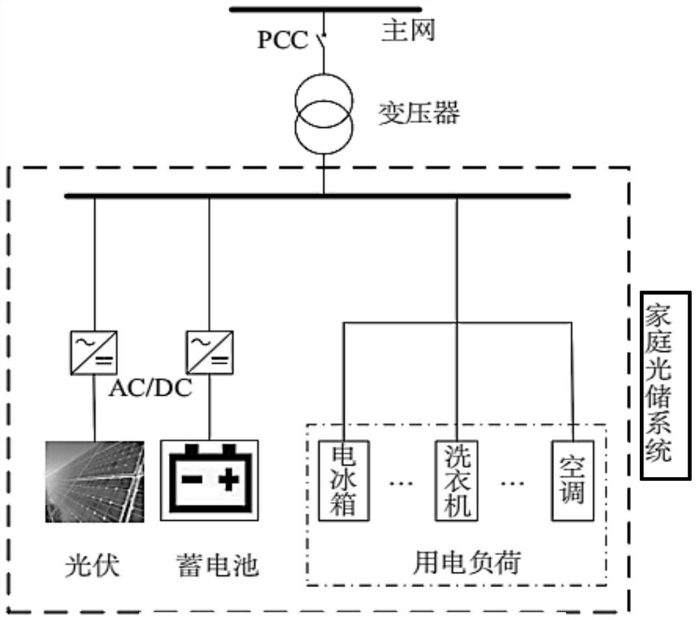
[0035] A control method for power exchange between the main network and the home optical storage system of the present application, such as figure 1 As shown, the household photovoltaic storage system includes household loads, photovoltaic power generation, and battery energy storage systems; the photovoltaic power generation and storage batteries are connected to their respective DC-AC converters, and each DC-AC converter is connected to the system's AC bus to realize the system's internal power generation equipment and loads. , Electric energy exchange between batteries.

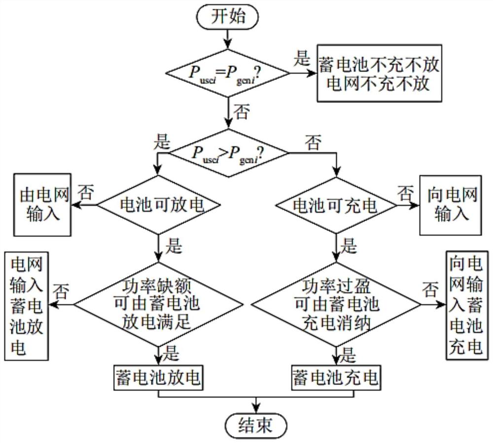
[0036] The amount of electric power exchanged between the main grid and the household solar storage system P exj ,Calculated as follows:

[0037] P exj =P usej -P genj -P batj (1);

[0038] In the formula, P usej Indicates the average household electricity load in the jth time period, P genj Indicates the average household power generation power in the jth time period, P batj Indicates the chargi...

specific Embodiment 2

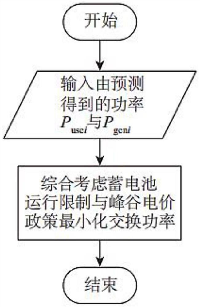
[0111] An embodiment of the present application provides a control terminal for power exchange between a main network and a household optical storage system. The terminal device in this embodiment includes: a processor, a memory, and a device stored in the memory and capable of running on the processor. A computer program, such as an optimization calculation program, when the processor executes the computer program, the control steps in Embodiment 1 are realized, such as figure 2 Steps shown:

[0112] Exemplarily, the computer program may be divided into one or more modules / units, and the one or more modules / units are stored in the memory and executed by the processor to complete the present application. The one or more modules / units may be a series of computer program instruction segments capable of completing specific functions, and the instruction segments are used to describe the control terminal of the computer program for power exchange between the main network and the ...

specific Embodiment 3

[0119] The module / unit integrated with the control terminal equipment for power exchange between the main network and the home optical storage system, if implemented in the form of a software function unit and sold or used as an independent product, can be stored in a computer-readable memory medium. Based on this understanding, all or part of the processes in the methods of the above embodiments in the present application can also be completed by instructing related hardware through computer programs. The computer programs can be stored in a computer-readable storage medium, and the computer When the program is executed by the processor, the steps in the above-mentioned various method embodiments can be realized. Wherein, the computer program includes computer program code, and the computer program code may be in the form of source code, object code, executable file or some intermediate form. The computer-readable medium may include: any entity or device capable of carrying ...


PUM


Abstract

The invention discloses a control method for power exchange between a main network and a household optical storage system. The household optical storage system comprises a household load, a photovoltaic power generation system and an energy storage system, when the load and the photovoltaic power generation power are unknown, a scheduling period is equally divided into M time intervals, and a power exchange target function in each time interval is calculated, thereby ensuring that the power exchange between the main network and the household optical storage system is minimum; and when the loadand the photovoltaic power generation power are known, the power exchange objective function between the main network and the household optical storage system is calculated by adopting a prediction method and taking the minimum electric power exchange amount between a family and the main network in one scheduling period as an objective, and an optimal planning scheme is obtained in combination with constraint conditions. By controlling the charging and discharging of the energy storage system, the dependence degree of the family on the main network is reduced, peak clipping and valley fillingeffects on household electricity are achieved, and meanwhile, energy flow between the main network and the household optical storage system is reduced, fluctuation of a power grid is reduced, and theelectric energy quality of the system is guaranteed.

Description

technical field [0001] The invention relates to the technical field of electric energy storage, in particular to a control method for power exchange between a main network and a household optical storage system. Background technique [0002] Photovoltaic power generation enters the home, and the excess electricity generated by the home is output to the main grid. When the home energy storage is insufficient, power is obtained from the main grid, and power exchange occurs between the home and the main grid. At present, most of the studies on the optimal control of household grid-connected photovoltaic power generation systems with energy storage start from the economic benefits of system operation, and seldom consider reducing household dependence on the grid and weakening the impact of grid-connected fluctuating renewable energy on the grid. Impact, improving the on-site consumption of renewable energy is the main research goal. Moreover, the access of large-scale distribut...

Claims


Application Information

Patent Timeline
Patent Type & Authority Applications(China)
IPC IPC(8): H02J3/00H02J3/32H02J3/38
CPCH02J3/00H02J3/32H02J3/381H02J3/008H02J2203/10H02J2203/20H02J2300/24Y02E10/56Y02E70/30Y02B10/10
Inventor 姚艳郭高鹏康家乐岑银伟汪雅静张志刚张帅江涵宋弘亮
Owner NINGBO ELECTRIC POWER DESIGN INST
Why Eureka
Try Eureka