
MEMS microphone chip

A microphone and chip technology, applied in the field of acoustics and electricity, can solve problems such as diaphragm fracture, MEMS microphone chip failure, and slow expansion, and achieve the effects of reducing adhesion, reducing contact area, and reducing pressure film damping

Inactive Publication Date: 2021-03-12
RUISHENG NEW ENERGY DEV CHANGZHOU +1
View PDF5 Cites 1 Cited by
  • Summary
  • Abstract
  • Description
  • Claims
  • Application Information

AI Technical Summary

Problems solved by technology

[0005] The above-mentioned dimple structure and the diaphragm process hole used to release the sacrificial layer will cause stress concentration. In loud application scenarios and mechanical reliability tests such as blowing and dropping, if the edge of the diaphragm and the sharp back cavity on the upper part of the base Foreign particles on the boundary or on the upper part of the substrate come into contact, and microcracks will be generated at the stress concentration point of the dimple structure of the diaphragm after contact 0
In repeated mechanical reliability tests such as loud sound pressure or air blowing and dropping, when the diaphragm 20' moves back and forth between the back plate 30' and the base 10', the stress the diaphragm bears is an alternating stress σ, At this point the initial microcrack a 0 Under the action of alternating stress σ, it will expand slowly, when the microcrack expands to a = a c When, the diaphragm will break, which will cause the failure of the MEMS microphone chip

Method used


Image

  • MEMS microphone chip
  • MEMS microphone chip

Examples


Embodiment Construction

[0016] The present invention will be further described below in conjunction with the accompanying drawings and embodiments.

[0017] It should be noted that all directional indications (such as up, down, left, right, front, back, inside, outside, top, bottom...) in the embodiments of the present invention are only used to explain As shown in the figure), if the relative positional relationship between the various components, etc., if the specific posture changes, the directional indication will also change accordingly.

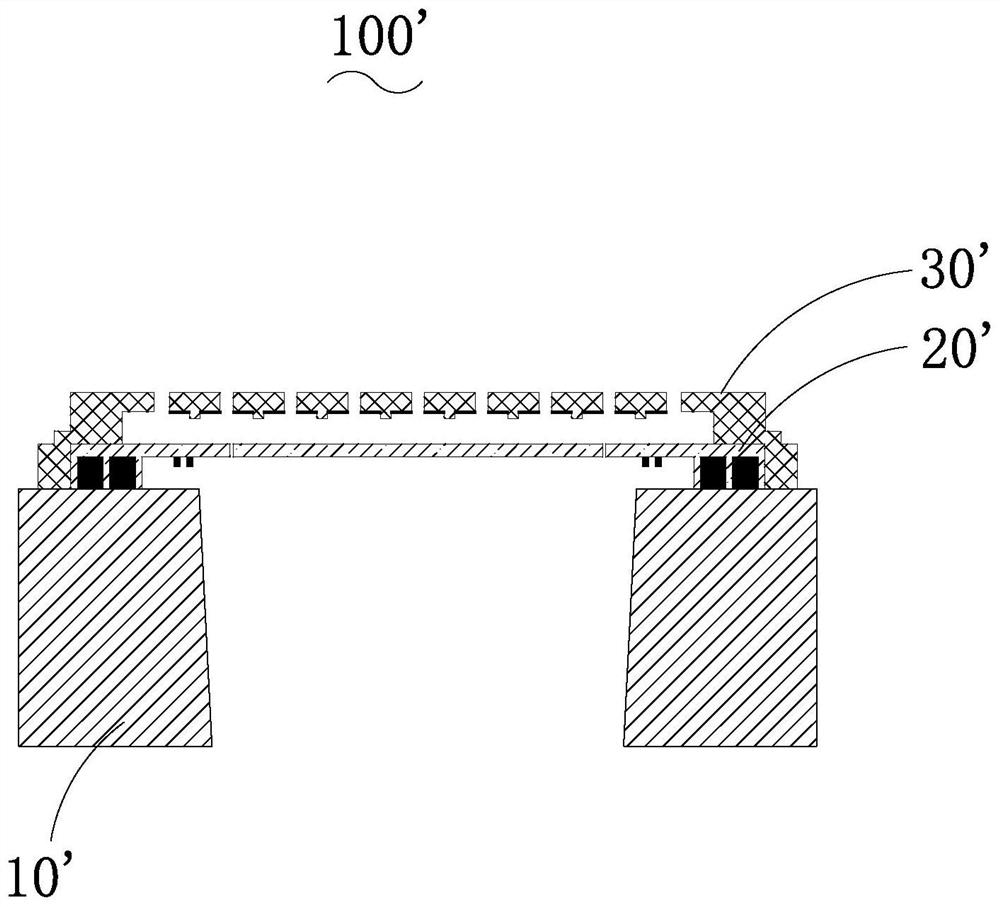
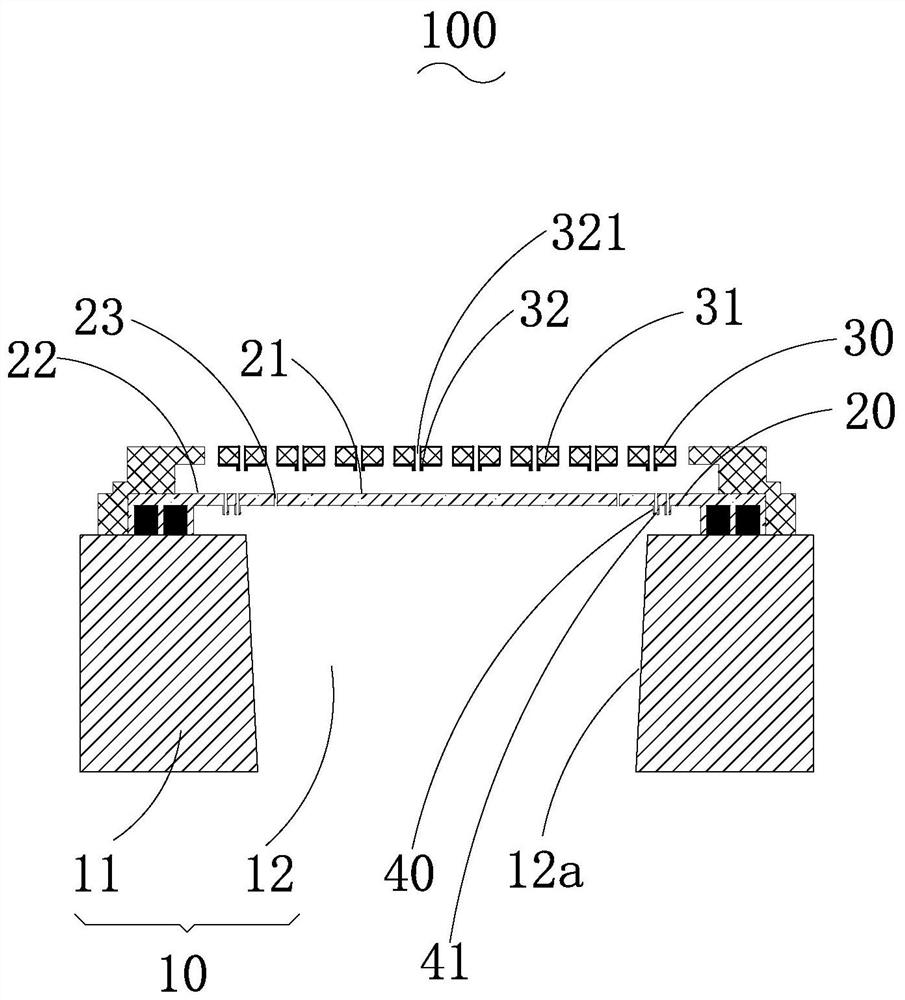
[0018] see figure 2 , the present invention provides a MEMS microphone chip 100, the chip 100 includes a substrate 10 with a back cavity 12, a diaphragm 20 and a back plate 30 sequentially arranged on the surface of the substrate 10.

[0019] The base 10 includes an annular base 11 surrounding the back cavity 12, the diaphragm 20 and the back plate 30 are fixed on the annular base 11, and the diaphragm 20 is arranged on the base 10 and the back plate. betwe...


PUM


Abstract

The invention provides an MEMS microphone chip. The MEMS microphone chip comprises a substrate with a back cavity, a vibrating diaphragm arranged on the substrate, and a back plate covering the vibrating diaphragm, wherein an inner cavity is formed between the back plate and the vibrating diaphragm; wherein the back plate extends towards the direction close to the vibrating diaphragm to form a first anti-sticking bulge which is separated from the vibrating diaphragm, and the back plate is provided with a first through hole which penetrates through the first anti-sticking bulge and the back plate. The first anti-sticking protrusions spaced from the vibrating diaphragm are formed on the back plate, when the vibrating diaphragm makes contact with the back plate, the contact area of the vibrating diaphragm and the back plate is reduced, the adhesive force is reduced, the vibrating diaphragm rebounds, electric field force and the adhesive force can be overcome more easily, and therefore thevibrating diaphragm is prevented from being stuck to the back plate in the vibrating process; furthermore, the back plate is provided with a first through hole penetrating through the first anti-sticking bulge and the back plate, so that the aperture ratio of the back plate is improved, the pressed film damping at the position of the back plate is reduced, and the signal-to-noise ratio of the microphone is improved.

Description

【Technical field】 [0001] The invention relates to the field of acoustic and electric technologies, in particular to a MEMS microphone chip. 【Background technique】 [0002] The application of MEMS microphone chips is becoming more and more extensive, and the reliability requirements for chips are also getting higher and higher. Taking a capacitive MEMS microphone chip as an example, the chip includes a substrate with a back cavity, and a diaphragm and a backplate structure on the upper part of the substrate, wherein the diaphragm and the backplate structure form a capacitive system. The external sound pressure causes the diaphragm to move through the through hole of the back plate structure, and this movement will change the distance between the diaphragm and the back plate structure, thereby changing the capacitance and finally converting it into an electrical signal. [0003] Such as figure 1 As shown, in a MEMS microphone chip 100' in the prior art, an anti-adhesion post...

Claims


Application Information

Patent Timeline
IPC IPC(8): H04R19/04
CPCH04R19/04H04R2201/003
Inventor 柏杨陈燕鑫张睿
Owner RUISHENG NEW ENERGY DEV CHANGZHOU
Features
  • Generate Ideas
  • Intellectual Property
  • Life Sciences
  • Materials
  • Tech Scout
  • Unparalleled Data Quality
  • Higher Quality Content
  • 60% Fewer Hallucinations
Learn More