Dust removal type ceramic grinding equipment

A technology of ceramics and equipment, which is applied in the field of dust-removing ceramic grinding equipment, can solve the problems of staff health threats, dust flying, etc., and achieve the effect of avoiding dust diffusion and ensuring stability

Inactive Publication Date: 2021-03-16
马朋飞
View PDF9 Cites 4 Cited by
  • Summary
  • Abstract
  • Description
  • Claims
  • Application Information

AI Technical Summary

Problems solved by technology

[0004] The purpose of the present invention is to solve the shortcomings of the existing ceramic grinding workpieces in the prior art that dust will fly when grinding, and there is a certain threat to the health of the staff, and a dust removal type ceramic grinding equipment is proposed.

Method used


Image

  • Dust removal type ceramic grinding equipment
  • Dust removal type ceramic grinding equipment
  • Dust removal type ceramic grinding equipment

Examples


Embodiment 1

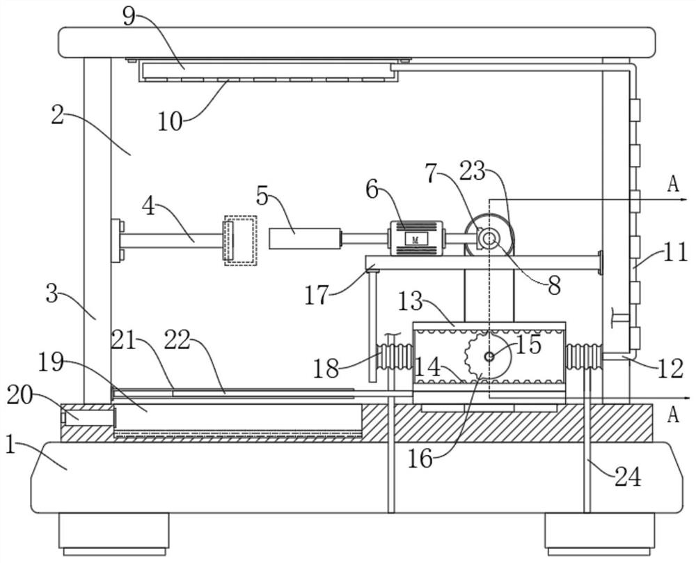
[0029] refer to Figure 1-4 , comprising a base 1, the upper end of the base 1 is fixedly connected with a grinding box 3, the grinding box 3 is provided with a processing chamber 2, and the right inner wall of the processing chamber 2 is fixedly connected with a horizontal plate 17, which can be installed on the front side of the grinding box 3 A sliding door for picking and placing ceramics that need to be polished;

[0030] A grinding mechanism is installed on the upper end of the horizontal plate 17, and the grinding mechanism is used for grinding ceramics;

[0031] The area below the horizontal plate 17 in the processing chamber 2 is provided with a blower mechanism, which is used to blow the dust generated by grinding;

[0032] The inner bottom of the processing chamber 2 is provided with an ash collection tank 19, and a dust collection mechanism matched with a blower mechanism is installed at the notch of the ash collection tank 19.

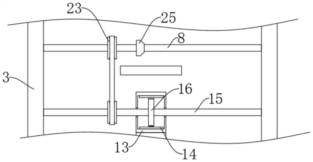
[0033] Wherein, the grinding mech...

Embodiment 2

[0046] refer to Figure 5 The difference between this embodiment and Embodiment 1 is that the ends of the two air inlet pipes 24 away from the corresponding airbags 18 both extend into the air outlet 20 .

[0047] In this embodiment, its functional principle can be explained through the following operation mode: when the gear box 13 moves left and right, it will absorb gas from the outside through the air inlet pipe 24, and when the end of the air inlet pipe 24 away from the corresponding air bag 18 extends to the air outlet 20 , so that the air outlet 20 produces a suction force, which forms a circulating airflow with the gas discharged from the air outlet 10, and the dust generated by grinding will move with the circulating airflow, which can further limit the movement direction of the dust (in order to observe the grinding direction during grinding) situation, the sliding door on the front side is open, if there is no circulating air flow, the situation of part dust flying ...


PUM


Abstract

The invention discloses dust removal type ceramic grinding equipment comprising a base. A grinding box is fixedly connected to the upper end of the base; a treatment chamber is arranged in the grinding box; a transverse plate is fixedly connected to the inner wall of the right side of the treatment chamber; a grinding mechanism is installed at the upper end of the transverse plate and used for grinding ceramic; the area, located below the transverse plate, of the treatment chamber is provided with an air blowing mechanism, and the air blowing mechanism is used for blowing dust generated by grinding; and an ash collecting groove is formed in the inner bottom of the treatment chamber, and a dust collecting mechanism matched with the air blowing mechanism is installed at a groove opening of the ash collecting groove. In the using process of the grinding equipment, the dust generated by grinding can be collected in a centralized mode, and the situation that the dust diffuses is effectivelyavoided.

Description

technical field [0001] The invention relates to the field of ceramic processing, in particular to a dust removal type ceramic grinding equipment. Background technique [0002] Porcelain is the collective name of pottery and porcelain, and it is also a kind of arts and crafts in our country. As far back as the Neolithic Age, there were rough and simple painted pottery and black pottery in our country. Pottery and porcelain have different textures and properties. As people With the improvement of living standards, all kinds of exquisite ceramic products appear in people's field of vision, and the polishing of ceramics is one of the processes of ceramic processing; [0003] The surface of the green body needs to be polished during grinding, so a large amount of fine dust that cannot be seen by the naked eye will be generated. Diseases, there are certain safety hazards, and at the same time, the final dust will fall inside the polished workpiece and on the ground of the factory...

Claims


Application Information

Patent Timeline
Patent Type & Authority Applications(China)
IPC IPC(8): B24B19/22B24B55/06B24B55/12
CPCB24B19/22B24B55/06B24B55/12
Inventor 马朋飞
Owner 马朋飞
Why Eureka
Try Eureka