Flat polishing machine for wafer processing

A polishing machine and surface cutting technology, which is applied in the direction of surface polishing machine tools, metal processing equipment, grinding/polishing equipment, etc., can solve problems such as burr splashing, polishing machine environmental pollution, etc.

Inactive Publication Date: 2021-03-16
临漳县澳皇网络科技有限公司
View PDF8 Cites 0 Cited by
  • Summary
  • Abstract
  • Description
  • Claims
  • Application Information

AI Technical Summary

Problems solved by technology

[0003] At present, there is a cutting surface polishing machine for wafer processing. When polishing the surface of the wafer, the polishing sheet and the cutting surface are constantly rubbed, so that the burrs generated in the cutting process are cut off and smoothed, so that the polishing blade is driven by the polishing knife. The burrs cut off from the bottom fly out along the moving direction of the polishing knife, causing the burrs to splash and pollute the environment near the polishing machine

Method used


Image

  • Flat polishing machine for wafer processing
  • Flat polishing machine for wafer processing
  • Flat polishing machine for wafer processing

Examples


Embodiment 1

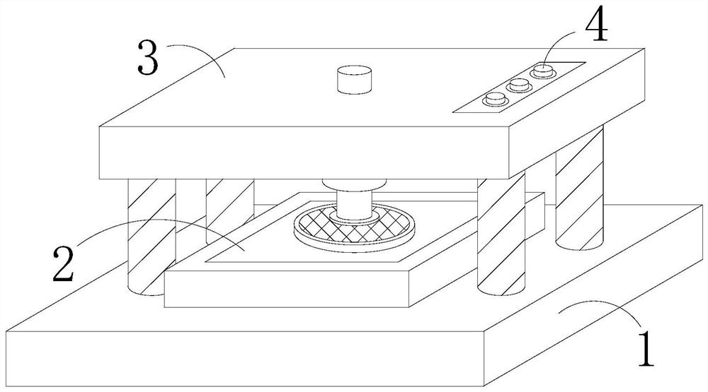
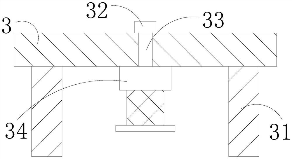
[0029] The present invention provides a surface polishing machine for wafer processing. Right above the workbench 1, the button 4 is embedded on the upper surface of the top plate 3. The top plate 3 includes a support rod 31, a turning block 32, a screw 33, and a polisher 34. The top of the support rod 31 is connected to the top plate by welding. 3 lower surface, and the bottom of the support rod 31 is embedded on the upper surface of the worktable 1, the rotating block 32 is installed just above the center of the top plate 3, the screw 33 is perpendicular to the center of the top plate 3 through bolts, and the top of the screw 33 is connected to the rotating The blocks 32 are welded together, the top of the polisher 34 is embedded in the lower surface of the top plate 3, there are four support rods 31, and the length of the polisher 34 after being extended is the shortest between the bottom of the top plate 3 and the upper surface of the polishing seat 2 The distance is conve...

Embodiment 2

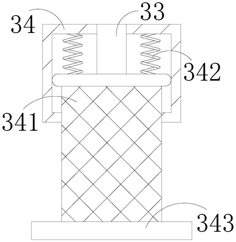
[0035]In the figure, the polisher 34 includes a telescopic rod 341, a tension spring 342, and a polishing knife 343. The telescopic rod 341 is connected to the inner bottom of the polisher 34 by a movable snap, and the tension spring 342 is connected to the telescopic rod 341 by welding. Between the top and the upper inner wall of the polisher 34, the upper surface of the polishing blade 343 is embedded in the bottom end of the telescopic rod 341, the interior of the polisher 34 is hollowed out, and the pulling force of the tension spring 342 is greater than the gravity of the telescopic rod 341, which is convenient for polishing After the knife 343 polishes the wafer, the telescopic rod 341 and the polishing knife 343 are pulled up by the pulling force of the tension spring 342 .

[0036] In the figure, the telescopic rod 341 includes a partition a1, an air extractor a2, a filter screen a3, a storage cylinder a4, and a through hole a5. The partition a1 is connected to the inne...


PUM


Abstract

The invention discloses a flat polishing machine for wafer processing. The flat polishing machine structurally comprises a workbench, a polishing seat, a top plate and a button, the bottom of the polishing seat is embedded and fixed on the upper surface of the workbench, the top plate is arranged right above the workbench, and the button is embedded and fixed on the upper surface of the top plate.The flat polishing machine has the beneficial effects that a cut wafer is placed on the polishing seat, a rotating block is rotated to drive a screw rod to rotate, so that a polishing knife polishesthe flat of a wafer, an air exhauster is started to upwards suck burrs removed and discharged in the polishing process into a storage barrel, when the air exhauster stops working, a baffle is closed to prevent the burrs from falling out to influence the environment near the polishing machine, the air exhauster is started to drive a rotating rod to rotate, the rotating rod drives a polishing blockto rotate, so that a brush rubs with the surface of the wafer to remove the burrs on the plat of the wafer, polish and grind the burrs, meanwhile, the cut burrs are shoveled up by an inclined scraper,so that the burrs are sucked into an isolation cavity conveniently, and are prevented from splashing everywhere due to the fact that the polishing block throws out the burrs.

Description

technical field [0001] The invention relates to the field of wafer coating, in particular to a surface polishing machine for wafer processing. Background technique [0002] Wafer refers to the silicon wafer used to make silicon semiconductor circuits. The processing process is to first add polysilicon sol and then add crystals to form cylindrical silicon ingots, then grind and cut to form wafers, and finally polish the wafers. The cut surface becomes smooth. [0003] At present, there is a cutting surface polishing machine for wafer processing. When polishing the surface of the wafer, the polishing sheet and the cutting surface are constantly rubbed, so that the burrs generated during the cutting process are cut off and smoothed, so that the driving force of the polishing knife The burrs that are cut off fly out along the moving direction of the polishing knife, causing the burrs to splash around and polluting the environment near the polishing machine. SUMMARY OF THE INV...

Claims


Application Information

Patent Timeline
Patent Type & Authority Applications(China)
IPC IPC(8): B24B29/02B24B9/06B24B47/14B24B41/06B24B41/04B24B55/06B24B55/12B08B1/04
CPCB08B1/005B08B1/04B24B9/065B24B29/005B24B29/02B24B41/04B24B41/06B24B47/14B24B55/06B24B55/12
Inventor 赵震
Owner 临漳县澳皇网络科技有限公司
Why Eureka
Try Eureka