Sedimentation tank plate cutting equipment for sewage treatment
A technology of cutting equipment and sewage treatment, which is applied in metal processing and other fields, can solve the problems of time-consuming, labor-intensive costs, low efficiency, etc., and achieve the effect of reducing labor costs and improving work efficiency
- Summary
- Abstract
- Description
- Claims
- Application Information
AI Technical Summary
Problems solved by technology
Method used
Image

Examples
Embodiment 1
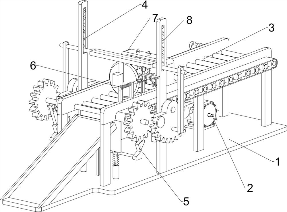
[0076] A sedimentation tank plate cutting equipment for sewage treatment, such as figure 1 , figure 2 , image 3 , Figure 4 , Figure 5 and Image 6 As shown, it includes a bottom plate 1, a first servo motor 2, a transmission mechanism 3, a cutting mechanism 4 and a material blocking mechanism 5. The first servo motor 2 is installed on the left side of the front part of the bottom plate 1, and the bottom plate 1 is provided with a transmission mechanism 3. , the transmission mechanism 3 is connected with the output shaft of the first servo motor 2, the base plate 1 is provided with a cutting mechanism 4, the cutting mechanism 4 is connected with the transmission mechanism 3, the base plate 1 is provided with a stopper mechanism 5, the stopper mechanism 5 is connected with the cutting mechanism 4 is connected, and the blocking mechanism 5 cooperates with the transmission mechanism 3.
[0077] Manual cutting of plates is inefficient, time-consuming and labor-intensive, a...
Embodiment 2
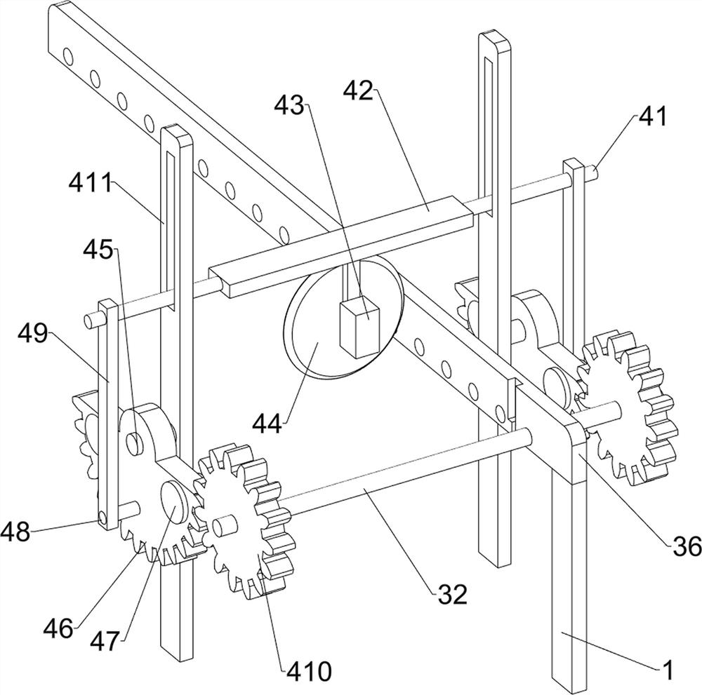
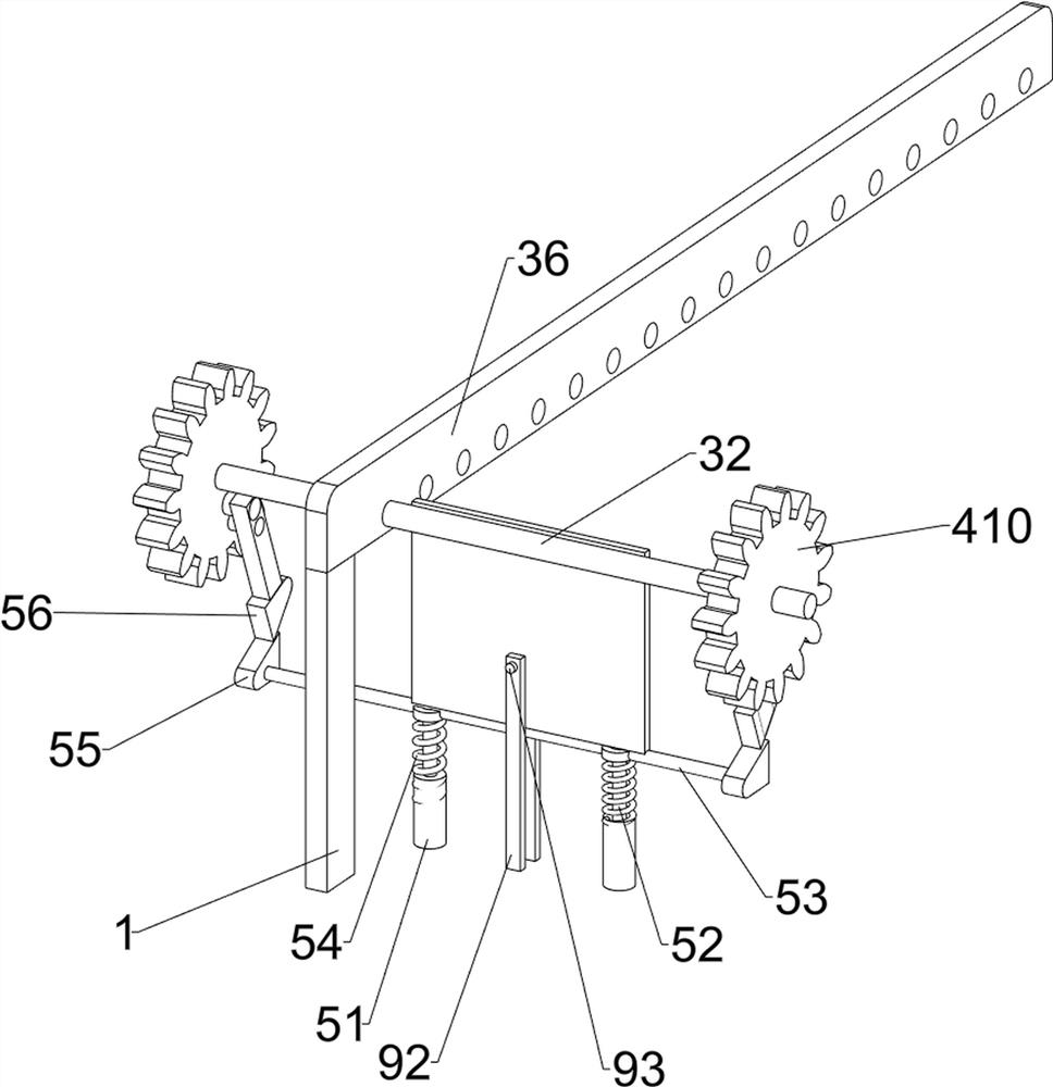
[0079] On the basis of Example 1, such as image 3 , Figure 4 , Figure 5 , Image 6 and Figure 7 As shown, the transmission mechanism 3 includes a first rotating shaft 31, a second rotating shaft 32, a rolling wheel 33, a first transmission assembly 34, a second transmission assembly 35, a baffle plate 36 and a blanking plate 37. A baffle plate 36 is provided, and the left part of the baffle plate 36 on the front and rear sides is rotatably connected with a first rotating shaft 31, and the front side of the first rotating shaft 31 is connected with the output shaft of the first servo motor 2 with a second transmission assembly 35, and the front and rear sides The right part of the baffle plate 36 is rotatably connected with a second rotating shaft 32, the second rotating shaft 32 is connected with the cutting mechanism 4, the first rotating shaft 31 and the second rotating shaft 32 are connected with two first transmission assemblies 34, and the first transmission assemb...
Embodiment 3
[0086] On the basis of Example 2, such as figure 1 , figure 2 , Figure 5 , Image 6 and Figure 7 As shown, it also includes a cooling mechanism 6, the baffle plate 36 on the rear side is provided with a cooling mechanism 6, the cooling mechanism 6 is connected with the mounting plate 411 and the baffle plate 53, the cooling mechanism 6 includes a third wedge block 61, a second The fixed sleeve 62, the first elastic member 63, the fourth wedge block 64, the fourth rotating shaft 65, the rotating block 66, the second fixed plate 67 and the water spray hose 68, the rear side of the top of the material retaining plate 53 is provided with a third wedge block 61, the third wedge block 61 is slidingly connected with the rear baffle 36, the top right side of the rear baffle 36 is provided with a second fixing sleeve 62, and the inside of the top of the second fixing sleeve 62 is slidingly provided with a first elastic member 63, the right side of the first elastic member 63 is ...
PUM
 Abstract
Description
Claims
Application Information
 - R&D
- Intellectual Property
- Life Sciences
- Materials
- Tech Scout
- Unparalleled Data Quality
- Higher Quality Content
- 60% Fewer Hallucinations
Browse by: Latest US Patents, China's latest patents, Technical Efficacy Thesaurus, Application Domain, Technology Topic, Popular Technical Reports.
© 2025 PatSnap. All rights reserved.Legal|Privacy policy|Modern Slavery Act Transparency Statement|Sitemap|About US| Contact US: help@patsnap.com