
Automatic edge removing machine

An edge removal machine and automatic technology, applied in the direction of stone processing tools, work accessories, manufacturing tools, etc., can solve the problems of not fast enough cutting, not so high, and the efficiency can not keep up with the demand, so as to simplify the cutting operation steps and avoid Cutting operation, the effect of improving effective work efficiency

Pending Publication Date: 2021-03-16
厦门海力拓自动化科技有限公司
View PDF1 Cites 0 Cited by
  • Summary
  • Abstract
  • Description
  • Claims
  • Application Information

AI Technical Summary

Problems solved by technology

The output force of the piston rod of the cylinder can be precisely adjusted through the electric proportional valve, so as to adjust the pressure of the knife seat module on the ceramic diaphragm. The adjustment is sensitive and convenient, and the pressure can be adjusted according to different ceramic diaphragms. Adjusting to the best state not only ensures that the ceramic diaphragm is pressed tightly, but also ensures the stability of the cutting, thereby ensuring the quality of the cutting; it also prevents the ceramic diaphragm from being crushed and causes additional damage to the ceramic diaphragm, but this The operation of the cutting machine is to remove the leftovers and cut the sides neatly. The base needs to change the angle continuously. When the four sides of the electronic components are to be dropped, it needs to be turned back and forth four times to avoid cutting crookedly. It is guaranteed, but the cutting speed is not fast enough. For electronic components that do not require high precision, the cutting efficiency cannot keep up with the demand.

Method used


Image

  • Automatic edge removing machine
  • Automatic edge removing machine
  • Automatic edge removing machine

Examples


Embodiment Construction

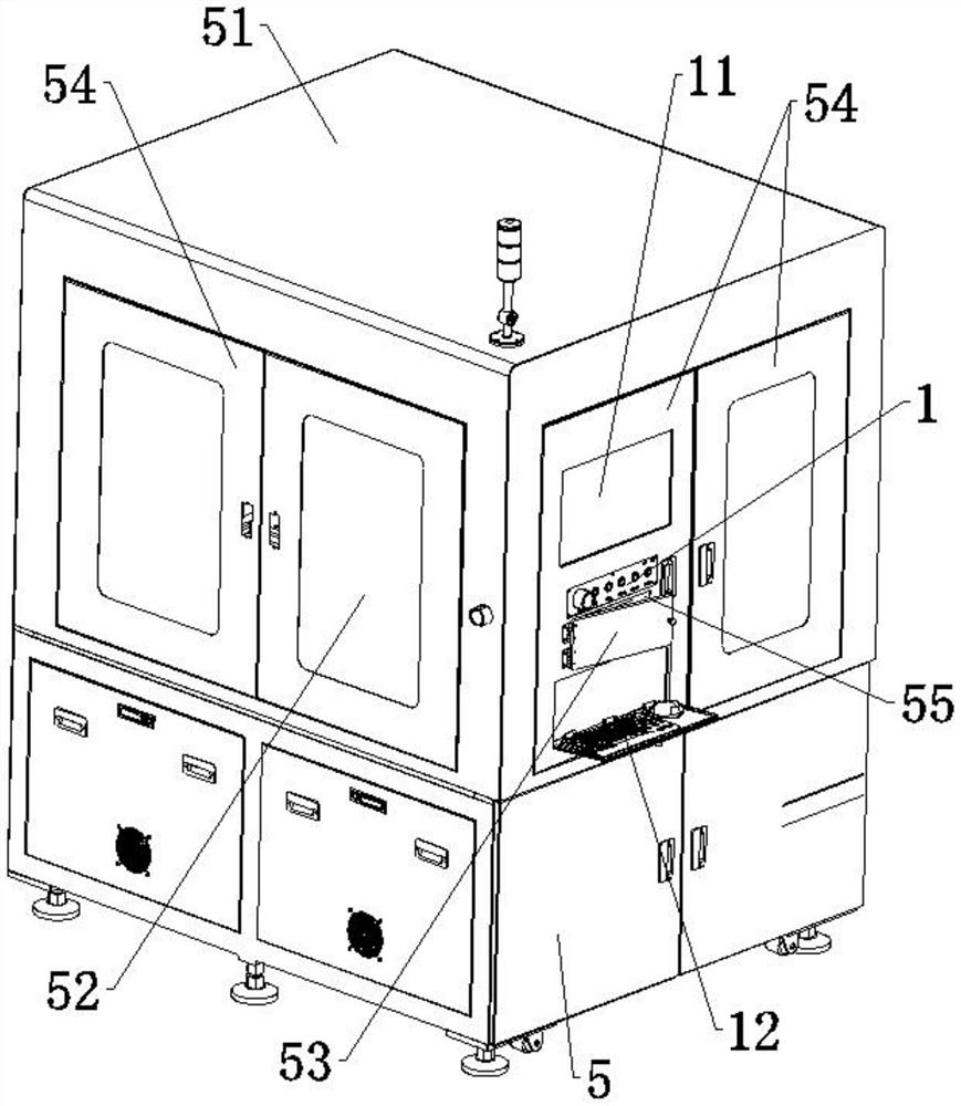
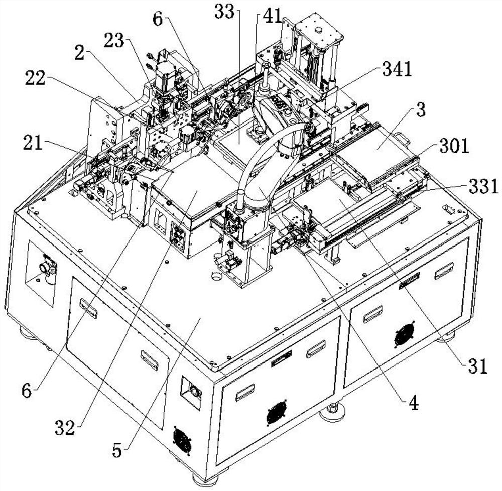
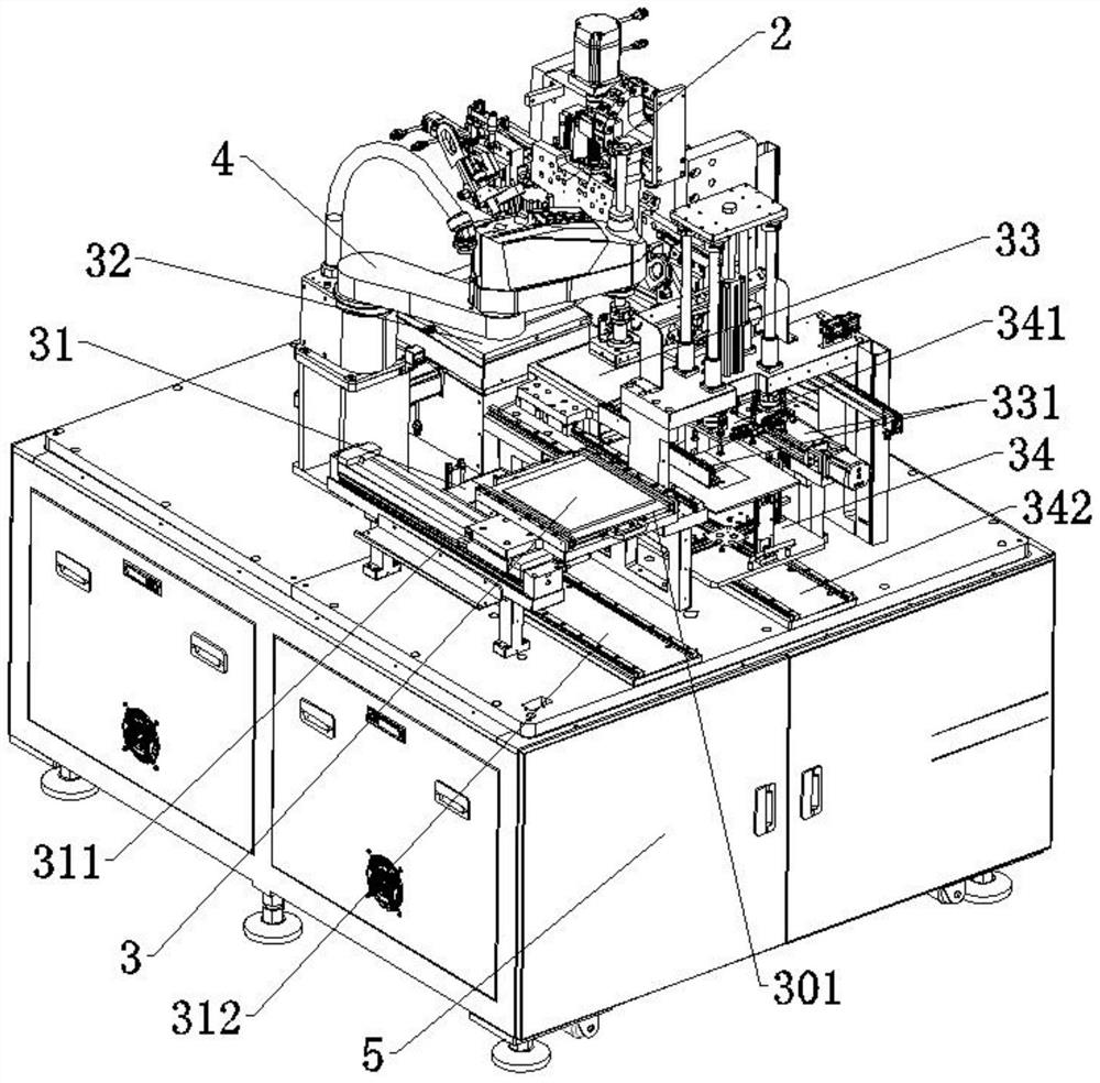
[0048] see Figures 1 to 14 As shown, the present invention provides a technical solution: an automatic edge removal machine, comprising:

[0049] The frame platform 5 is erected stably on a plane, and a protection cabinet 51 is fixed above it, and cabinet doors 54 are arranged on four sides of the protection cabinet 51, and observation windows 52 are inlaid on each of the cabinet doors 54, one of which A material extraction port 55 is provided on the cabinet door 54, and a material extraction cover 53 that can be opened is locked on the material extraction port 55;

[0050] The mechanical arm 4 is fixedly installed on the frame table 5, and its clamping end is a mechanical arm suction cup 41;

[0051] The waste table 3, the finished product table 31, the cutting table 32, the feeding table 33 and the raw material bin 34 are all arranged inside the protection cabinet 51, and the waste table 3 is installed on the waste positioning slide rail 311 through the waste slide rail 30...


PUM

PropertyMeasurementUnit
diameteraaaaaaaaaa

Abstract

The invention discloses an automatic edge removing machine in the technical field of chip electronic component processing, which comprises a rack table stably erected on a plane; a protection cabinetis fixedly arranged above the rack table; cabinet doors are arranged on four sides of the protection cabinet, an observation window is embedded on each cabinet door, and a material taking opening is arranged on one of the cabinet doors; a material taking cover capable of being opened is locked on the material taking opening; a rotating platform deck is removed, the platform deck does not need to do reciprocating motion, the platform deck does not need to rotate each time to adjust the angle of an electronic component, a CCD detector and a mechanical arm are matched with each other, the angle of the electronic component can be adjusted more quickly, the position is accurate, meanwhile, the device can initially identify the state of electronic component raw materials and identify whether theelectronic component raw materials belong to defective scrapped raw materials or not, if the electronic component raw materials belong to the scrapped raw materials, the device does not need to complete cutting, the scrapped raw materials are directly classified, distinguished and collected through the mechanical arm, and more unnecessary operation steps are omitted.

Description

technical field [0001] The invention relates to the technical field of chip electronic component processing, in particular to an automatic edger. Background technique [0002] With the development of science and technology, there are more and more varieties of electronic products, increasingly powerful functions, and smaller and smaller volumes. This requires that the main electronic components in the manufacture of electronic products, such as capacitors, resistors, inductors, sensors, etc., should be as small as possible and their reliability should be as high as possible. At present, chip ceramic electronic components are mainly used, and their insulation, heat resistance, durability and other aspects all show excellent performance. Therefore, the manufacture, sale and use of chip ceramic electronic components have been vigorously developed. [0003] When manufacturing chip ceramic electronic components, a cutting machine is required to cut the ceramic diaphragm to obta...

Claims


Application Information

Patent Timeline
Patent Type & Authority Applications(China)
IPC IPC(8): B28D1/22B28D7/00B28D7/02B28D7/04
CPCB28D1/222B28D7/005B28D7/02B28D7/04
Inventor 王一鸣罗光裕
Owner 厦门海力拓自动化科技有限公司
Learn More