Supercharge Your Innovation With Domain-Expert AI Agents!

Foaming box

A box-body, integrated technology, applied to conveyor objects, household components, household appliances, etc., can solve the problems of unreasonable structural design of turning equipment, easy collision of boxes, and installation on the back or bottom of electrical appliances.

Inactive Publication Date: 2021-03-16
安徽智汇和科技服务有限公司
View PDF10 Cites 0 Cited by
  • Summary
  • Abstract
  • Description
  • Claims
  • Application Information

AI Technical Summary

Problems solved by technology

[0002] The electrical cabinets such as refrigerators and freezers generally use foaming technology to form an insulation layer between the outer shell and the inner tank. When foaming, a pouring hole should be reserved on the outer shell. However, the processing of the pouring hole in the prior art has the following defects: First, the pouring hole is generally located on the back or bottom of the appliance, so many manufacturers do not do any treatment on the pouring hole after foam molding or simply seal it with tape. After long-term use of the appliance, it is easy to cause the foam layer to become damp and mildewed In addition, the pouring hole also lacks effective means of sealing during the foaming process. After the foaming is completed, a large amount of foaming agent often overflows from the pouring hole, which increases the difficulty of cleaning; It is necessary to clean the foaming agent overflowing from the surface of the box and the liner. During the cleaning process, the box needs to be turned over. The existing turning equipment is prone to impact during the turning process, which will cause damage to the surface of the box. Damage; In addition, the structure design of the existing turning equipment is unreasonable, the mechanism stroke is long, and the action efficiency is low

Method used


Image

  • Foaming box
  • Foaming box
  • Foaming box

Examples


Embodiment 1

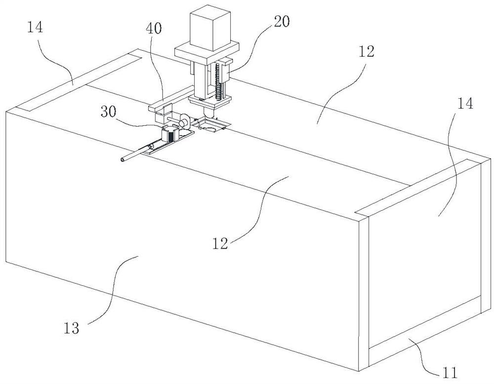
[0052] A box body foaming system includes a foaming device and a cleaning device, and a box conveying line is arranged between the foaming device and the cleaning device; figure 1 As shown, the foaming device includes a foaming mold, and the foaming mold includes a top plate 12, a bottom plate 11, two end plates 14, two side plates 13 and a mold core, wherein the top plate 12 is parallel to the bottom plate, and the two end plates 14 are parallel to each other. The two side plates 13 are parallel to each other, and the top plate 12, the bottom plate 11, the two end plates 14, and the two side plates 13 jointly form a rectangular cavity. The mold core is fixed on the bottom plate 11, and the two side plates 13 and the bottom plate 11 wherein The two opposite sides are hinged, and the other two opposite sides of the two end plates 14 are hinged with the bottom plate 11; The plate 13 is fixedly connected; a gap is provided at the joint where the two halves of the top plate 12 are...

Embodiment 2

[0063] A kind of foam box body, adopts the system described in embodiment 1 to make, and manufacturing method is:

[0064] Step 1: Fix the inner tank and the outer shell of the box into one body, so that the outer shell and the inner tank travel in a closed cavity; and reserve a pouring hole 2 for pouring foaming agent on the outer shell;

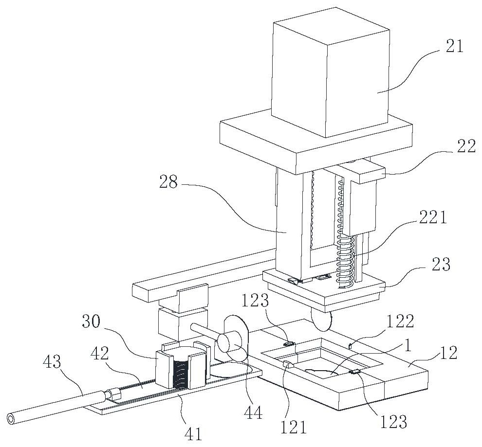
[0065] Step 2: Put the foaming agent pouring hole 2 of the box upwards and place it in the foaming mold; before placing the box, first unfold the side plate 13 and the end plate 14 of the mold, and then set the box on the mold core, Then the side panels 13 and the end panels 14 are brought together, and clamps are used to clamp the seams of the panels; on the top panel 12, a gap is reserved for pouring foaming agent and installing the sealing sheet 1, which is compatible with the foaming agent. The position of pouring hole 2 is corresponding;

[0066] Step 3: pour the foaming agent from the foaming agent pouring hole 2 to the sandwich cavi...


PUM


Abstract

The invention belongs to the technical field of electric appliance production and manufacturing, and particularly relates to a foaming box. The foaming box is prepared by the following method including the steps of 1, fixedly connecting an inner container and an outer shell of the box into a whole, 2, placing a foaming agent pouring hole of the box in a foaming mold upwards, 3, pouring a foaming agent, 4, mounting a hole sealing piece on the inner side of the foaming agent pouring hole, 5, loosening the hole sealing piece, 6, expanding the mold again, 7, cleaning the foaming agent overflowingfrom the back face and the side face of the box, 8, overturning the box until the front face is upward and 9, cleaning the front face of the box and the surface of the inner container. A hole sealingdevice is additionally arranged on the basis of an existing foaming mold, the hole sealing piece is placed on the inner side of the pouring hole through the hole sealing device, the hole sealing piececan be tightly attached to the inner side plate face of the box through extrusion of the foaming agent after the foaming agent achieves foaming, and the phenomenon that a foaming layer is wet and mildewed due to the fact that moisture permeates into the foaming layer can be effectively avoided.

Description

technical field [0001] The invention belongs to the technical field of electric appliance production and manufacturing, and in particular relates to a foam box body. Background technique [0002] The electrical cabinets such as refrigerators and freezers generally use foaming technology to form an insulation layer between the outer shell and the inner tank. When foaming, a pouring hole should be reserved on the outer shell. However, the processing of the pouring hole in the prior art has the following defects: First, the pouring hole is generally located on the back or bottom of the appliance, so many manufacturers do not do any treatment on the pouring hole after foam molding or simply seal it with tape. After long-term use of the appliance, it is easy to cause the foam layer to become damp and mildewed In addition, the pouring hole also lacks effective means of sealing during the foaming process. After the foaming is completed, a large amount of foaming agent often overflo...

Claims


Application Information

Patent Timeline
Patent Type & Authority Applications(China)
IPC IPC(8): B29C44/18B29C44/58B29C44/60B29C44/56B65G47/88B65G47/248B65G13/00
CPCB29C44/18B29C44/56B29C44/58B29C44/581B29C44/60B29L2031/7622B65G13/00B65G47/248B65G47/8823
Inventor 廖玉琴
Owner 安徽智汇和科技服务有限公司
Features
  • R&D
  • Intellectual Property
  • Life Sciences
  • Materials
  • Tech Scout
  • Unparalleled Data Quality
  • Higher Quality Content
  • 60% Fewer Hallucinations
Learn More