Textile dye coating device

A coating device and dye technology, applied in the processing of textile materials, liquid/gas/steam textile material processing, textiles and papermaking, etc., can solve the problems of low coating efficiency, waste of materials, waste of time, etc., to achieve operational Simple, saving coating cost, improving work efficiency

Pending Publication Date: 2021-03-16
孙晓梅
View PDF0 Cites 2 Cited by
  • Summary
  • Abstract
  • Description
  • Claims
  • Application Information

AI Technical Summary

Problems solved by technology

[0005] Aiming at the deficiencies of the prior art, the present invention provides a dye coating device for textiles, which is easy to operate, and can be coated when the cloth is sensed, and the switch of the coating device is closed in the gap between the cloth, saving materials and saving Cost, replace manual operation, improve work efficiency, solve the problem of existing coating devices, often place the device to be coated on the conveyor belt, and apply it through the coating device on the top, but in this way, different pieces of cloth Coating will cause a waste of materials. By manually controlling the switch of the coating device, the operation is troublesome, time-wasting, and the coating efficiency is low.

Method used


Image

  • Textile dye coating device
  • Textile dye coating device
  • Textile dye coating device

Examples


Embodiment Construction

[0024] The following will clearly and completely describe the technical solutions in the embodiments of the present invention with reference to the accompanying drawings in the embodiments of the present invention. Obviously, the described embodiments are only some, not all, embodiments of the present invention. Based on the embodiments of the present invention, all other embodiments obtained by persons of ordinary skill in the art without making creative efforts belong to the protection scope of the present invention.

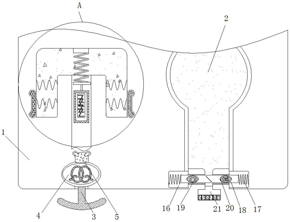
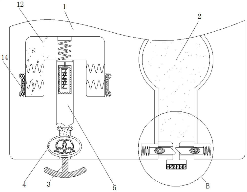
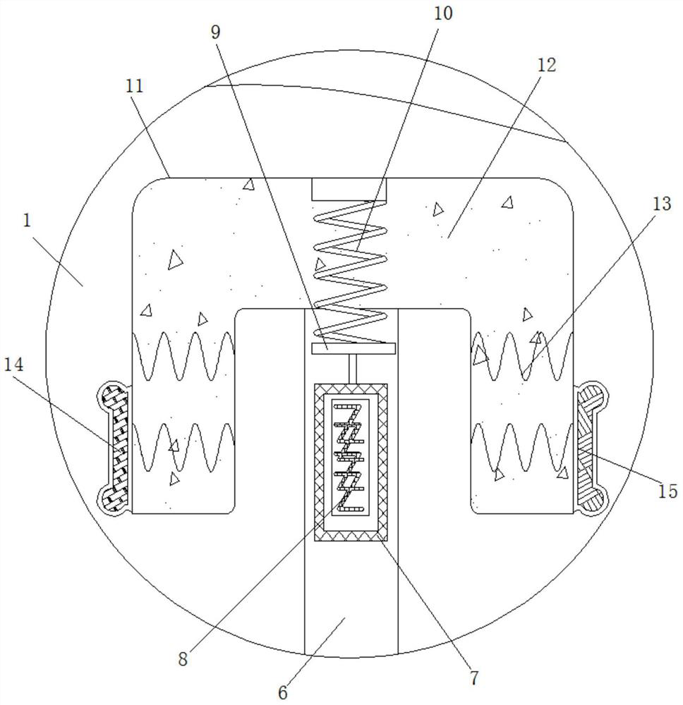
[0025] see Figure 1-4 , a dye coating device for textiles, comprising a housing 1, a paint chamber 2 and a sealed chamber 11, the bottom of the housing 1 is plugged with a movable plate 3, the inside of the paint chamber 2 is filled with PVC paint, and the bottom outlet of the paint chamber 2 The diameter is less than the diameter of the paint chamber 2, and the outlet diameter is equal to the feed inlet diameter of the paint brush 21, the paint can enter the...


PUM


Abstract

The invention relates to the technical field of textile fabric coating, and discloses a textile dye coating device. The textile dye coating device comprises a shell, a coating cavity and a sealing cavity; a movable plate is inserted into the bottom of the shell; a piezoelectric crystal is movably connected to the top of the movable plate; a first electromagnet is fixedly connected to the top of the piezoelectric crystal; a limiting groove is formed in the shell; a dielectric plate is movably connected into the limiting groove; and a first magnetic block is fixedly connected into the dielectricplate. According to the textile dye coating device, when tablecloth passes through the bottom of the shell, the movable plate moves upwards to extrude the piezoelectric crystal, so that currents aregenerated on the two sides of the piezoelectric crystal; the first electromagnet is electrified to push the dielectric plate to move upwards, and currents are generated between a positive plate and anegative plate, so that two limiting blocks move towards the two sides; and the interior of the coating cavity is filled with PVC coating, so that the tablecloth can be coated from the bottom of a coating brush, operation is easy, cost is saved, manual operation is replaced, and the working efficiency is improved.

Description

technical field [0001] The invention relates to the technical field of textile cloth coating, in particular to a textile dye coating device. Background technique [0002] Textile fabrics need to be further coated after the material is processed. Among them, after the textile tablecloth is coated with PVC material, a layer of film is formed on the surface to protect the tablecloth, which can make the surface of the fabric smooth and shiny, with a better hand feeling, and can be anti-wrinkle and waterproof , has resilience, the existing coating device usually places the device to be coated on the conveyor belt, and coats it through the coating device on the top, but this will cause waste of materials when coating different pieces of cloth . [0003] By manually controlling the switch of the coating device, the operation is cumbersome, time-consuming, and the coating efficiency is low. Therefore, we propose a textile dye coating device to solve the above problems. The contact ...

Claims


Application Information

Patent Timeline
IPC IPC(8): D06B1/12D06B23/00D06N3/00
CPCD06B1/12D06B23/00D06N3/0088
Inventor 孙晓梅李嘉浩周鹏程
Owner 孙晓梅
Why Eureka
Try Eureka