Hydraulic milling and drilling machine and working method thereof

A hydraulic milling and drilling rig technology, which is applied in the field of rock milling and drilling, can solve the problems of low efficiency and poor operation stability, and achieve the effects of good working stability, low construction cost and high milling and drilling efficiency

Pending Publication Date: 2021-03-16
安徽铁创新材料科技有限公司 +1
View PDF0 Cites 2 Cited by
  • Summary
  • Abstract
  • Description
  • Claims
  • Application Information

AI Technical Summary

Problems solved by technology

[0004] The purpose of the present invention is to provide a hydraulic milling and drilling machine and its working meth

Method used


Image

  • Hydraulic milling and drilling machine and working method thereof
  • Hydraulic milling and drilling machine and working method thereof

Examples


Example Embodiment

[0018] DRAWINGS The present application will be further described in detail, it is necessary to point out that the following detailed description only for the present application is further illustrated not to be construed as limiting the scope of the present application protection, the skilled in the art can the contents of the above applications to make some non-essential improvements and adjustments to this application.
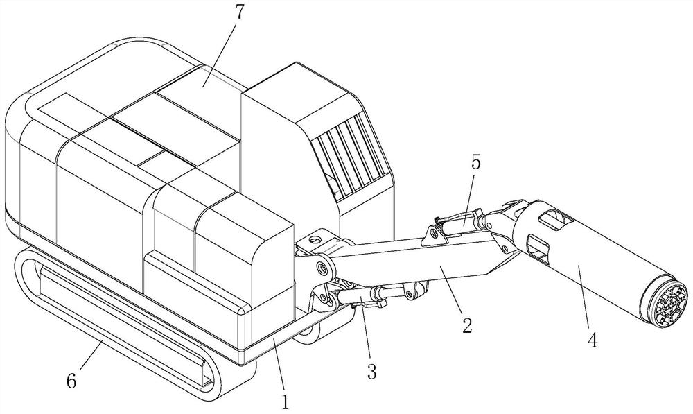
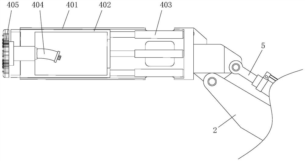
[0019] Combine figure 1 and figure 2 Shown, a hydraulic milling drill, comprises a movable body 1, 2 also comprises a boom, arm cylinder 3, milling and drilling assembly 4 and the attitude adjustment cylinder 5, the arm 2 is rotatably connected to the front end of the body 1, a swing arm a cylinder body 3 and a bottom end rotatably connected to arm 3 and the output end of the boom cylinder 2 is rotatably connected, milling and drilling assembly 4 is rotatably connected to the front end of the boom 2, attitude adjustment cylinder 5 and the bottom end of the boom...


PUM


Abstract

The invention discloses a hydraulic milling and drilling machine and a working method thereof. The hydraulic milling and drilling machine comprises a movable machine body and further comprises a largearm, a swing arm oil cylinder, a milling and drilling assembly and a posture adjusting oil cylinder, the large arm is rotatably connected to the front end of the machine body, the bottom end of the swing arm oil cylinder is rotatably connected with the machine body, the output end of the swing arm oil cylinder is rotatably connected with the large arm, the milling and drilling assembly is rotatably connected to the front end of the large arm, the bottom end of the posture adjusting oil cylinder is rotatably connected with the large arm, and the output end of the posture adjusting oil cylinderis rotatably connected with the milling and drilling assembly. The milling and drilling machine is good in working stability during milling and drilling, is hydraulically driven, is strong in power and high in milling and drilling efficiency, can be suitable for crushing, milling and drilling large-volume rocks, and is low in construction cost and good in construction environment.

Description

technical field [0001] The invention relates to the technical field of rock milling and drilling, in particular to a hydraulic milling and drilling machine and a working method thereof. Background technique [0002] In various operations such as mining, tunneling, roadway construction, etc., it is often faced with the entire rock. Since it is necessary to carry out hollowing operations inside the mountain, and because there is no free surface relative to the crushing direction, the construction has caused great damage. Difficult, the usual construction methods include explosives, hammering rock drilling, etc. Among them, the use of explosive blasting has many limitations and cannot be used in many construction environments. The hammer rock drilling method has the disadvantages of low efficiency, high noise, and a lot of dust, especially when encountering hard rock. [0003] For this reason, the process of milling and drilling first, and then crushing can be used to realize ...

Claims


Application Information

Patent Timeline
IPC IPC(8): E21D9/10E21B3/02E21B7/02E21B15/00
CPCE21B3/02E21B7/025E21B15/00E21D9/10E21D9/1086E21D9/1093
Inventor 曾可琴王建朱长伟王姣
Owner 安徽铁创新材料科技有限公司
Why Eureka
Try Eureka