

Double-side clamping type motor self-locking mechanism and self-locking motor
A self-locking motor and side clamp technology, applied in electrical components, electromechanical devices, electric components, etc., can solve the problems of output shaft jamming, reduce motor rotational stability, self-locking effect, and hidden safety hazards, and improve self-locking. Stability, excellent working stability, avoid the effect of self-locking force change
- Summary
- Abstract
- Description
- Claims
- Application Information
AI Technical Summary
Problems solved by technology
Method used
Image

Examples
Embodiment 1
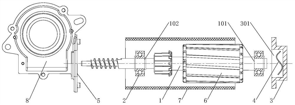
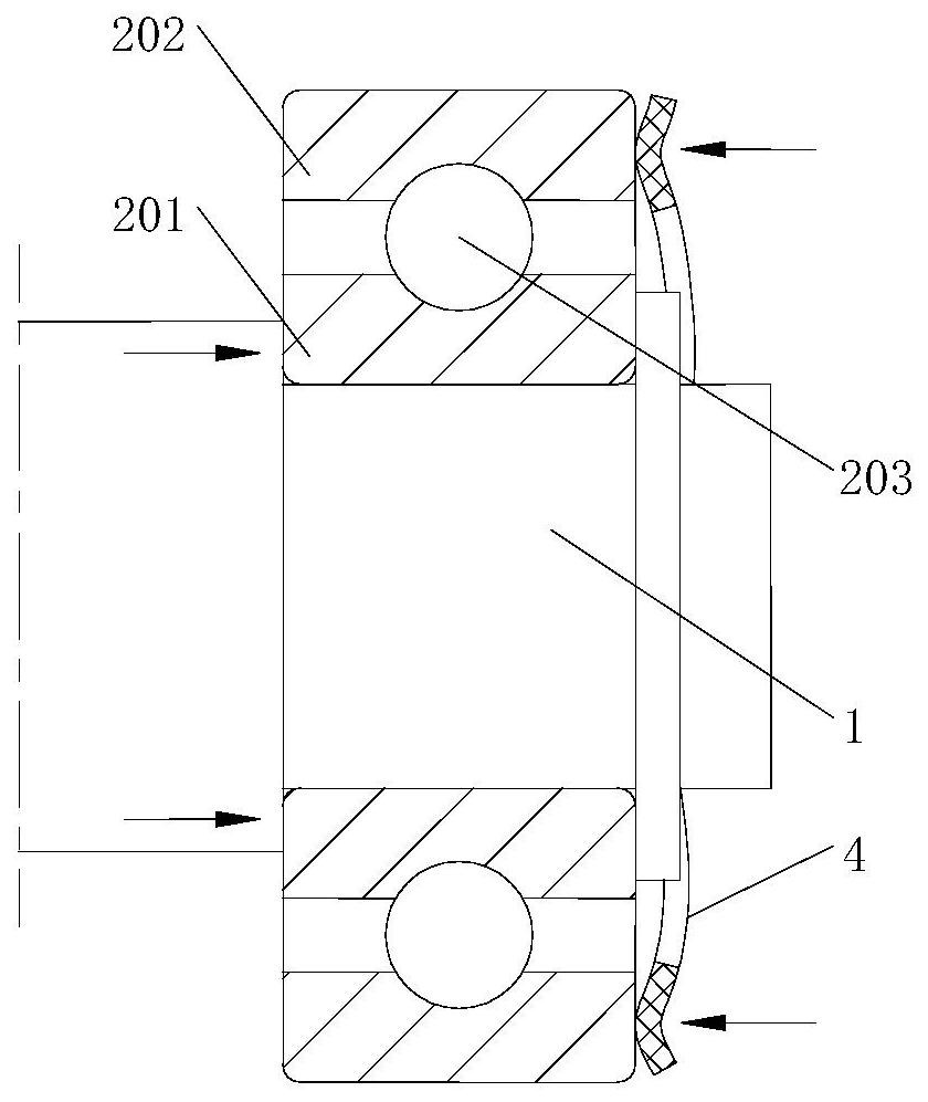
[0030] Example 1. A double-sided clamping motor self-locking mechanism, which is composed of Figure 1-2 As shown, the rotating shaft 1 is included, and the ball bearing 2 is arranged on the rotating shaft 1. The ball bearing 2 is a conventional bearing with an inner ring 201, an outer ring 202 and balls 203. The outer side of the ball bearing 2 is connected with an extruded part. The ball bearing The inner ring 201 and the outer ring 202 of 2 respectively exert axial pressing force on the balls 203 after being squeezed by the extrusion part.
[0031] The directions in which the inner ring 201 of the ball bearing 2 and the outer ring 202 of the ball bearing 2 exert pressure on the balls 203 are opposite to each other.
[0032] The number of the ball bearings 2 is two, and the two ball bearings 2 are respectively arranged on the left and right sides of the rotating shaft 1; the extruding part includes a first extruding group and a second extruding group, the first extruding gr...
Embodiment 2
[0043] Example 2. A single-side clamping motor self-locking mechanism, which is composed of figure 2 As shown, the rotating shaft 1 is included, and the ball bearing 2 is arranged on the rotating shaft 1. The ball bearing 2 is a conventional bearing with an inner ring 201, an outer ring 202 and balls 203. The outer side of the ball bearing 2 is connected with an extruded part. The ball bearing The inner ring 201 and the outer ring 202 of 2 respectively exert axial pressing force on the ball 203 after being squeezed by the extrusion part.
[0044] The directions in which the inner ring 201 of the ball bearing 2 and the outer ring 202 of the ball bearing 2 exert pressure on the balls 203 are opposite to each other.
[0045] The ball bearing 2 is arranged on one side of the rotating shaft 1 .
[0046] The extrusion part includes a cover plate 3 and a first extrusion surface 101 located on the rotating shaft 1, the cover plate 3 and the outer ring 202 on one side of the ball be...
PUM
 Abstract
Description
Claims
Application Information