Intelligent temperature control device for industrial automation system
A technology of industrial automation and temperature control devices, which is applied in household refrigeration devices, energy industry, sustainable manufacturing/processing, etc., can solve the problems of machine parts damage and the inability to confirm whether the machine has completely cooled down, etc., to achieve increased speed and long service life , strong anti-corrosion effect
- Summary
- Abstract
- Description
- Claims
- Application Information
AI Technical Summary
Problems solved by technology
Method used
Image


Examples
Embodiment 1
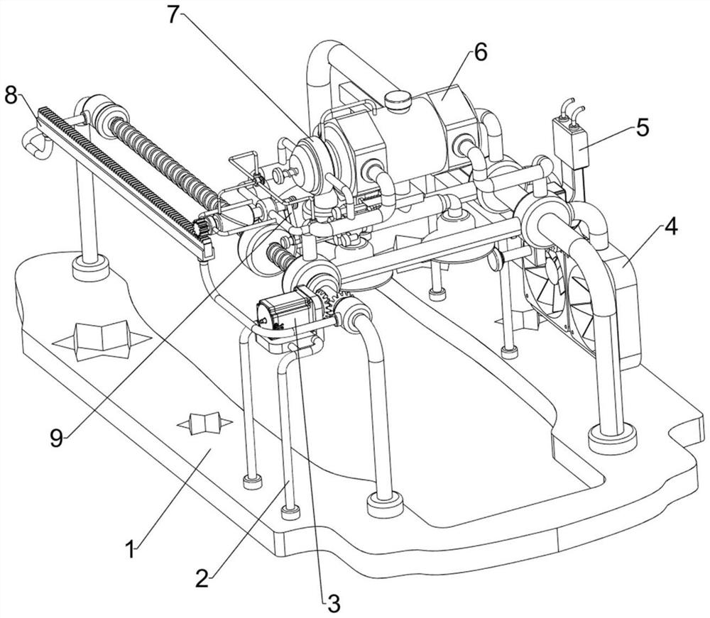
[0068] An intelligent temperature control device for an industrial automation system, such as figure 1 As shown, it includes a base plate 1, a base 2, a motor 3, a cooling mechanism 4 and a detection mechanism 5. The base plate 1 is provided with a base 2, the base 2 is equipped with a motor 3, the base plate 1 is provided with a cooling mechanism 4, and the cooling mechanism 4 A detection mechanism 5 is provided between the bottom plate 1 and the bottom plate 1.
[0069]When people need to cool down the machine in the factory, people place the machine in the factory between the left and right sides of the bottom plate 1, and the machine is detected by the detection mechanism 5. When people need to cool down the machine, people put the motor 3 is turned on, so that the output shaft of the motor 3 drives the detection mechanism 5 and the cooling mechanism 4 to move. At this time, the detection mechanism 5 no longer detects the machine, and then the cooling mechanism 4 completel...
Embodiment 2
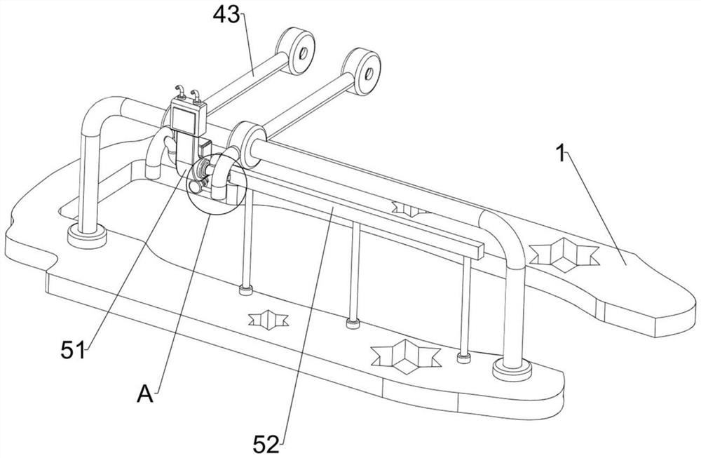
[0071] On the basis of Example 1, such as figure 2 As shown, the cooling mechanism 4 includes a first bracket 41, a screw rod 42, a threaded seat 43, a bevel gear set 44, a slide bar 45 and a fan 46, and the base plate 1 is symmetrically provided with the first bracket 41 front and rear, and the left side A screw rod 42 is rotatably provided between the two first brackets 41, a slide bar 45 is provided between the two first brackets 41 on the right side, and a threaded seat is provided on the front and rear sides of the slide bar 45 and the screw rod 42 in a sliding manner. 43, a bevel gear set 44 is arranged between the screw rod 42 and the output shaft of the motor 3, and a fan 46 is installed between the right sides of the two threaded seats 43.
[0072] When the machine needs to cool down the machine after the detection by the detection mechanism 5 is completed, people turn on the motor 3, so that the output shaft of the motor 3 drives the bevel gear set 44 to rotate, and...
Embodiment 3
[0074] On the basis of Example 2, such as figure 1 , image 3 , Figure 4 , Figure 5 , Image 6 , Figure 7 with Figure 8 As shown, the detection mechanism 5 includes a temperature measuring instrument 51, a first wedge block 52, a movable rod 53, a first spring 54 and a second wedge block 55, and a temperature measuring instrument 51 is arranged between the right sides of the two threaded seats 43, The upper right side of the bottom plate 1 is provided with a first wedge-shaped block 52, and the sliding type at the bottom of the temperature measuring instrument 51 is provided with a movable rod 53. The temperature measuring instrument 51 is connected, and a second wedge-shaped block 55 is connected to the rear side of the movable rod 53 , and the second wedge-shaped block 55 cooperates with the first wedge-shaped block 52 .
PUM
 Abstract
Description
Claims
Application Information
 - R&D
- Intellectual Property
- Life Sciences
- Materials
- Tech Scout
- Unparalleled Data Quality
- Higher Quality Content
- 60% Fewer Hallucinations
Browse by: Latest US Patents, China's latest patents, Technical Efficacy Thesaurus, Application Domain, Technology Topic, Popular Technical Reports.
© 2025 PatSnap. All rights reserved.Legal|Privacy policy|Modern Slavery Act Transparency Statement|Sitemap|About US| Contact US: help@patsnap.com