
Clamp for aero-engine blade vibration fatigue test

An aero-engine and vibration fatigue technology, which is applied in vibration testing, machine/structural component testing, manufacturing tools, etc., can solve problems such as blade vibration fatigue failure, avoid test invalidity, improve reliability, and improve clamping stability sexual effect

Inactive Publication Date: 2021-03-16
AVIC BEIJING INST OF AERONAUTICAL MATERIALS
View PDF8 Cites 3 Cited by
  • Summary
  • Abstract
  • Description
  • Claims
  • Application Information

AI Technical Summary

Problems solved by technology

However, the current blade clamping device and clamping method cannot fully meet the above-mentioned clamping reliability requirements, and the failure of the blade vibration fatigue test caused by the clamping problem occurs from time to time.

Method used


Image

  • Clamp for aero-engine blade vibration fatigue test
  • Clamp for aero-engine blade vibration fatigue test
  • Clamp for aero-engine blade vibration fatigue test

Examples


Embodiment Construction

[0017] The technical scheme of the present invention will be described in further detail below in conjunction with accompanying drawing and embodiment:

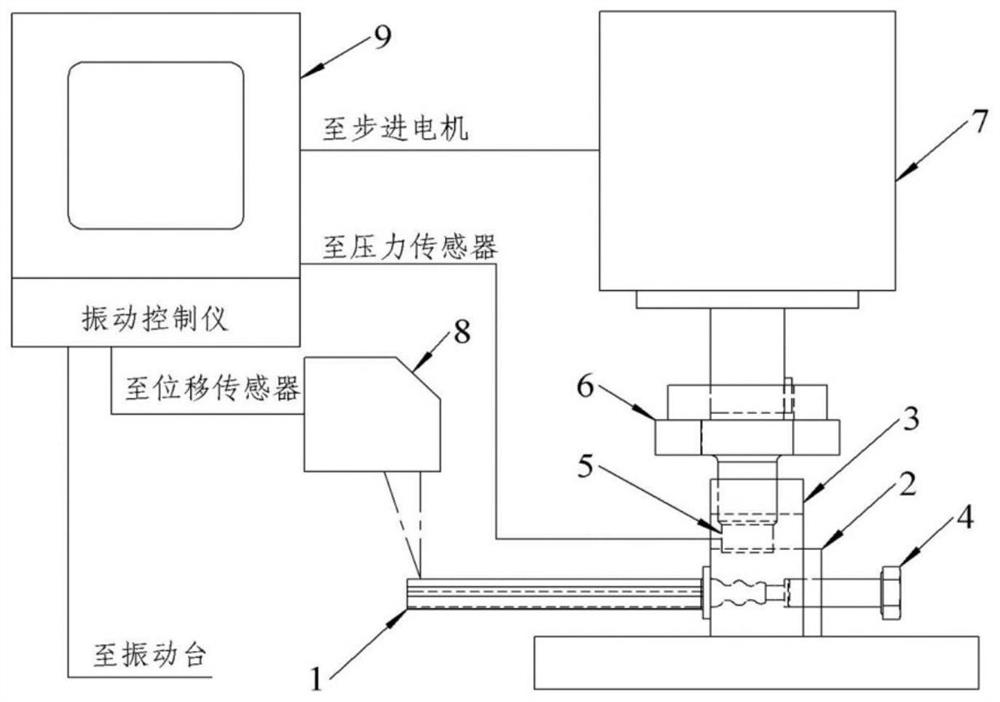
[0018] See attached Figures 1 to 4 As shown, the fixture used for the vibration fatigue test of the aeroengine blade includes a fixture 2, a support frame 3, a pressure sensor 5, a force applying bolt 6, a stepper motor 7, a laser displacement sensor 8 and a vibration controller 9, wherein: the fixture 2 is used to clamp the blade 1, the clamp 2 is fixed on the exciting plane of the vibrating table through the supporting frame 3, the stepping motor 7 is installed on a vertical lifting platform, and the stepping motor 7 drives the force applying bolt 6 to rotate and exert pressure on The clamp 2 is used to clamp the blade 1, and a pressure sensor 5 is arranged between the force-applying bolt 6 and the clamp 2 to simultaneously measure the downward force of the force-applying bolt 6, and the stepping motor 7 has a torque measu...


PUM


Abstract

The invention relates to a clamp for an aero-engine blade vibration fatigue test, which comprises a clamp (2), a supporting frame (3), a pressure sensor (5), a force application bolt (6), a stepping motor (7), a laser displacement sensor (8) and a vibration control instrument (9), and is characterized in that the clamp (2) is used for clamping a blade (1) and is fixed on a vibration excitation plane of a vibration table through the supporting frame (3), the stepping motor (7) drives the force application bolt (6) to rotate and apply pressure to the clamp (2) to clamp the blade (1), the pressure sensor (5) is arranged between the force application bolt (6) and the clamp (2) to synchronously measure the downward pressure of the force application bolt (6), and the laser displacement sensor (8) is used for measuring the amplitude of the blade (1) in the vibration fatigue test process. According to the clamp, the clamping force of the blade can be quantitatively given while the root of theblade is reliably clamped, the clamping force of the blade is monitored in real time, test invalidation caused by too large or too small clamping force of the blade is avoided, the clamping stabilityof vibration fatigue of the blade is remarkably improved, and the reliability of the blade vibration fatigue test is improved.

Description

technical field [0001] The invention is a multi-functional fixture used for the vibration fatigue test of an aero-engine blade, which belongs to the technical field of mechanical performance testing and characterization. Background technique [0002] Vibration is the most common form of load on an aeroengine blade during its service. The fatigue damage caused by vibration must be considered in the blade strength design process in order to effectively improve its service safety and reliability. Conducting vibration fatigue tests on aeroengine blades and obtaining performance data is not only a necessary assessment link in the development and production of blades, but also an important means for blade strength design and life prediction. [0003] The vibration fatigue test of the blade has to go through a long test period (usually lasting several days or even weeks) and a high loading frequency (usually hundreds to thousands of Hertz), so higher requirements are put forward f...

Claims


Application Information

Patent Timeline
Patent Type & Authority Applications(China)
IPC IPC(8): G01M7/02B25B11/00
CPCG01M7/02B25B11/00
Inventor 许巍陈新杨宪峰仲朝锋王亮何玉怀陶春虎
Owner AVIC BEIJING INST OF AERONAUTICAL MATERIALS
Features
  • Generate Ideas
  • Intellectual Property
  • Life Sciences
  • Materials
  • Tech Scout
  • Unparalleled Data Quality
  • Higher Quality Content
  • 60% Fewer Hallucinations
Learn More