Automatic chip removal filter screen for chemical pipeline

A chemical pipeline and automatic drainage technology, applied in the chemical industry, can solve the problems of manual and regular cleaning of chemical pipelines, reduce work efficiency, and many chemical pipelines, so as to avoid the influence of liquid flow rate, reduce the accident rate, and improve work efficiency. Effect

Inactive Publication Date: 2021-03-19
刘秋芳
View PDF6 Cites 1 Cited by
  • Summary
  • Abstract
  • Description
  • Claims
  • Application Information

AI Technical Summary

Problems solved by technology

[0002] The main material of chemical pipelines is ultra-high molecular weight polyethylene, which has excellent comprehensive properties, wear resistance, low temperature resistance, corrosion resistance, self-lubrication, and impact resistance are the highest among all plastics. There are many impurities and sediments in chemical pipelines. Existing chemical pipelines are mostly removed by setting a filter at the outlet. Long-term chip removal will cause more sediment to accumulate on the filter, causing blockage and requiring manual cleaning.
[0003] The solution flowing through the existing chemical pipeline will be accompanied by sediment and impurities. Long-term chip removal will cause the sediment to accumulate on the filter screen, which will cause blockage of the chemical pipeline, reduce the flow rate of the solution in the chemical pipeline, and cause Increase the accident rate of chemical pipelines, reduce work efficiency, and then require manual cleaning of chemical pipelines on a regular basis, which is time-consuming and laborious

Method used


Image

  • Automatic chip removal filter screen for chemical pipeline
  • Automatic chip removal filter screen for chemical pipeline
  • Automatic chip removal filter screen for chemical pipeline

Examples


Embodiment Construction

[0024] The following will clearly and completely describe the technical solutions in the embodiments of the present invention with reference to the accompanying drawings in the embodiments of the present invention. Obviously, the described embodiments are only some, not all, embodiments of the present invention. Based on the embodiments of the present invention, all other embodiments obtained by persons of ordinary skill in the art without making creative efforts belong to the protection scope of the present invention.

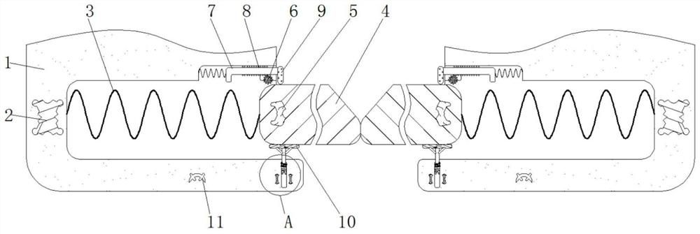
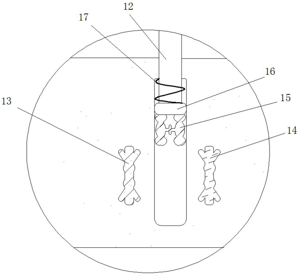
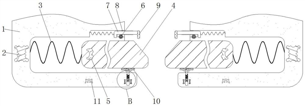
[0025] see Figure 1-4 , an automatic chip removal filter for chemical pipelines, comprising a housing 1, the inner wall of the housing 1 is fixedly connected with an electromagnet 2, the magnetism of the electromagnet 2 is opposite to that of the opposite surface of the magnetic plate 5, and the electromagnet 2 and the pressure sensitive The resistance 11 is electrically connected, the electromagnet 2 and the magnetic plate 5 have played a role of mutual attr...


PUM


Abstract

The invention relates to the technical field of chemical engineering, and discloses an automatic chip removal filter screen for a chemical pipeline. The automatic chip removal filter screen comprisesa shell, and is characterized in that an electromagnet is fixedly connected to the inner wall of the shell, a spring I is fixedly connected to the inner wall of the shell and close to the inner wall of the electromagnet, a filter screen is fixedly connected to the inner side of the spring I, a magnetic plate is fixedly connected to the inner wall of the filter screen, a gear ring is movably connected to the inner wall of the shell, a connecting rod is elastically connected to the portion, which is close to the outer side of the gear ring, of the inner wall of the shell, a gear block is fixedlyconnected to the outer side of the connecting rod, and a baffle is fixedly connected to the inner side of the connecting rod. According to the automatic chip removal filter screen for the chemical pipeline, sediment is accumulated on the filter screen due to long-time chip removal through the principle of a piezoresistor, blockage of the chemical pipeline is prevented, the flow rate of a solutionin the chemical pipeline is increased, the accident rate of the chemical pipeline is reduced, the working efficiency is improved, then automatic sediment removal is achieved, and the time and labor are saved.

Description

technical field [0001] The invention relates to the technical field of chemical industry, in particular to an automatic debris removal filter net for chemical pipelines. Background technique [0002] The main material of chemical pipelines is ultra-high molecular weight polyethylene, which has excellent comprehensive properties, wear resistance, low temperature resistance, corrosion resistance, self-lubrication, and impact resistance are the highest among all plastics. There are many impurities and sediments in chemical pipelines. Existing chemical pipelines are mostly removed by setting a filter at the outlet. Long-term chip removal will cause more sediment to accumulate on the filter, causing blockage and requiring manual cleaning. [0003] The solution flowing through the existing chemical pipeline will be accompanied by sediment and impurities. Long-term chip removal will cause the sediment to accumulate on the filter screen, which will cause blockage of the chemical pip...

Claims


Application Information

Patent Timeline
Patent Type & Authority Applications(China)
IPC IPC(8): B01D29/94B01D29/96F16L55/24
CPCB01D29/94B01D29/96B01D2201/4069F16L55/24
Inventor 刘秋芳
Owner 刘秋芳
Why Eureka
Try Eureka