

Automobile turbine shaft manufacturing process
A manufacturing process and turbine shaft technology, applied in the direction of manufacturing tools, grinding workpiece supports, metal processing equipment, etc., can solve the problems of machine sliding surface wear, mechanism stuck, action failure, etc., to ensure grinding quality, efficiency, convenience, etc. The effect of positioning and clamping and preventing wear
- Summary
- Abstract
- Description
- Claims
- Application Information
AI Technical Summary
Problems solved by technology
Method used
Image

Examples
Embodiment Construction
[0030] In order to make the technical means, creative features, goals and effects achieved by the present invention easy to understand, the present invention will be further elaborated below in conjunction with specific drawings. It should be noted that, in the case of no conflict, the embodiments and Features in the embodiments can be combined with each other.
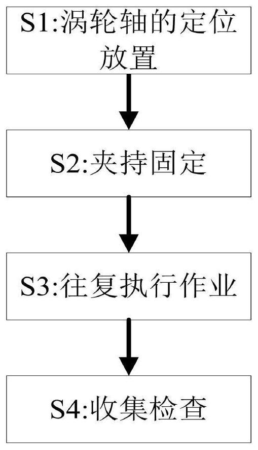
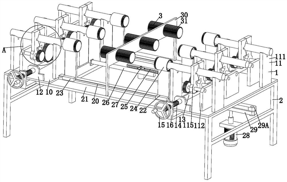
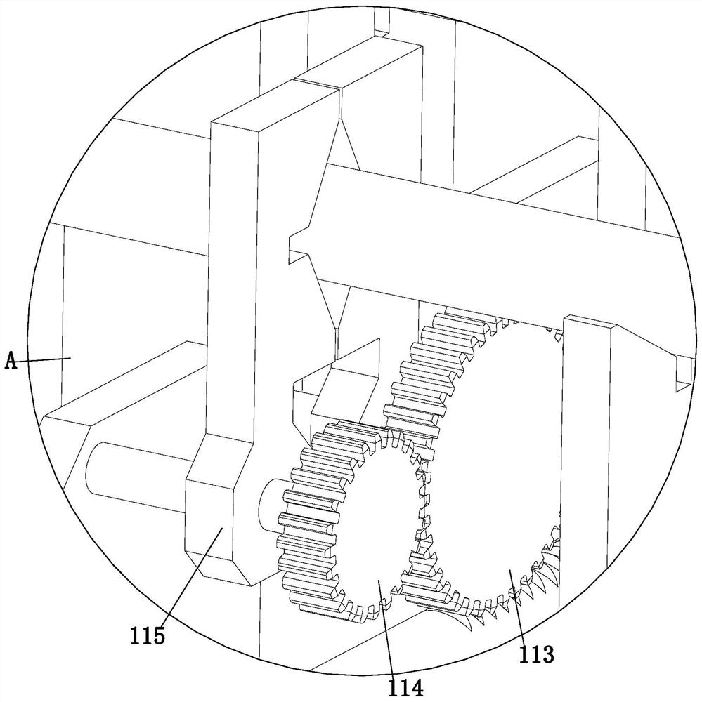
[0031] Such as Figure 1 to Figure 8 As shown, a manufacturing process of an automobile turboshaft, which uses automobile turboshaft manufacturing equipment, the manufacturing equipment includes a clamping mechanism 1, an actuator 2 and a polishing mechanism 3, and the burrs of the automobile turboshaft are polished using the above-mentioned manufacturing equipment The specific method is as follows:
[0032] S1. Positioning and placement of the turbine shaft: place the turbine shaft to be polished on the supporting bracket 111 through a special fixture;
[0033] S2. Clamping and fixing: lock and fix the turbine shaf...
PUM
 Abstract
Description
Claims
Application Information