Dust removal device for textile cloth

A dust removal device and dust brushing technology, which is applied in the direction of combined devices, textile and papermaking, and separation of dispersed particles, can solve the problems of polluting the delivery room environment and endangering the health of operators, so as to improve the environment, avoid dust floating, and ensure health. Effect

Inactive Publication Date: 2021-03-19
王凤娇
View PDF0 Cites 0 Cited by
  • Summary
  • Abstract
  • Description
  • Claims
  • Application Information

AI Technical Summary

Problems solved by technology

After the textile fabric is processed, it must be dedusted. The dedusting of the textile fabric is helpful for the storage of the textile fabric and ensures the quality of the textile fabric. The existing dedusting device for textile fabric generally uses a dedusting brush to remove the thread ends, Brush off the dust directly, and the brushed dust will pollute the environment in the delivery room and endanger the health of the operators.

Method used


Image

  • Dust removal device for textile cloth
  • Dust removal device for textile cloth
  • Dust removal device for textile cloth

Examples


Embodiment 1

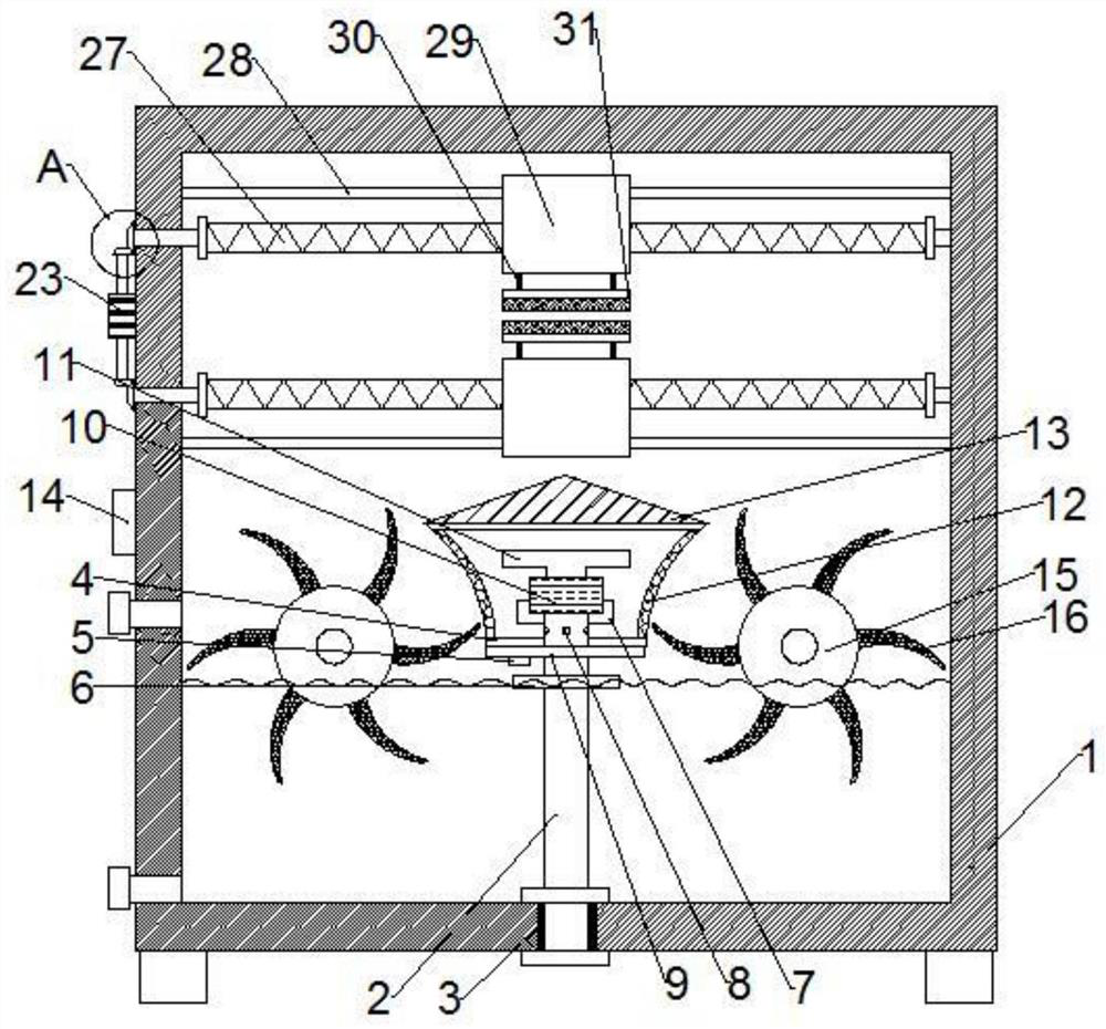
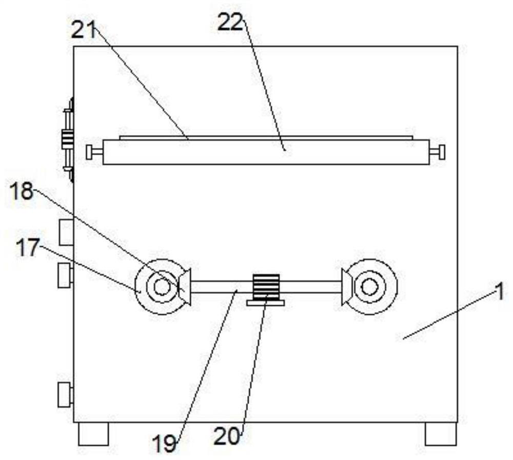
[0019] see Figure 1-3 , a dust removal device for textile cloth, comprising a main body 1, through holes 21 are respectively provided on the front and rear shell walls of the main body 1, and a dust brushing mechanism and a dust stopping mechanism are arranged on the inner side of the main body 1, and the The dust brushing mechanism is located on the upper side of the dust-removing mechanism, and the dust-removing mechanism includes a drum 15. The bottom side of the main body 1 is provided with a water storage chamber, and a water level alarm mechanism is provided in the water storage chamber. The main body 1 The bottom side of the hollow pillar 2 is fixedly interspersed with a hollow pillar 2, the bottom end of the hollow pillar 2 passes through the bottom side shell wall of the main body 1, and the upper end of the hollow pillar 2 is fixedly inserted in the support box 4, and the support box 4 is located at the upper end of the support plate 9, and the support plate 9 is fi...

Embodiment 2

[0027] see Figure 1-3, this embodiment is further optimized on the basis of Embodiment 1. Specifically, the water level alarm mechanism includes an inductor 5, and a sliding sleeve 6 is provided on the hollow pillar 2 inserted in the main body 1, so The bottom end of the support plate 9 is fixedly provided with an inductor 5, the outside of the main body 1 is provided with an alarm 14, and the sliding sleeve 6 can slide on the hollow pillar 2, and the sliding sleeve 6 is placed in the water. Moving upwards under the action of buoyancy, when the sliding sleeve 6 is in contact with the sensor 5, the alarm 14 will be triggered to alarm, thereby avoiding too much water in the main body 1.


PUM


Abstract

The invention discloses a dust removal device for a textile cloth, and belongs to the technical field of textiles. The dust removal device comprises a main body, a dust brushing mechanism and a dust stopping mechanism are arranged on the inner side of the main body, the dust brushing mechanism is located on the upper side of the dust stopping mechanism, the dust stopping mechanism comprises a rotary drum, a water storage cavity is formed in the bottom side of the main body, and a water level alarm mechanism is arranged in the water storage cavity. Dust can be brought into water through the dust stopping mechanism, so that the dust can be stopped, the dust is located in the water, the dust can be prevented from drifting, the environment of a delivery room can be improved, and the health ofoperators is guaranteed; by arranging the dust brushing mechanism, the upper surface and the lower surface of the textile cloth can be subjected to dust removal simultaneously, and the working efficiency can be improved; and the water level alarm mechanism is arranged, so that excessive water in the main body can be avoided.

Description

technical field [0001] The invention relates to the technical field of textiles, in particular to a dust removal device for textile cloth. Background technique [0002] The original meaning of textile is taken from the general term of spinning and weaving, but with the continuous development and improvement of the textile knowledge system and subject system, especially after the emergence of non-woven textile materials and three-dimensional composite weaving technologies, the current textile is not only a traditional Hand spinning and weaving also include garment, industrial and decorative textiles produced by non-woven technology, modern three-dimensional weaving technology, and modern electrostatic nano-netting technology. After the textile fabric is processed, it must be dedusted. The dedusting of the textile fabric is helpful for the storage of the textile fabric and ensures the quality of the textile fabric. The existing dedusting device for textile fabric generally use...

Claims


Application Information

Patent Timeline
IPC IPC(8): D06G1/00B01D50/00
CPCD06G1/00B01D50/60
Inventor 王凤娇
Owner 王凤娇
Why Eureka
Try Eureka