Fabricated side plate joint of steel beam and concrete-filled steel tube vertical element

A technology of concrete-filled steel tubes and vertical components, which is applied to building components, elongated structural components used for load-bearing, joists, etc., can solve the problems affecting the ultimate bearing capacity of connections, the need to improve the seismic performance, and the insufficient construction rate of nodes. , to solve the difficulty of tightening, the impact on the environment is small, and the construction efficiency is improved.

Pending Publication Date: 2021-03-19
CHINA SOUTHWEST ARCHITECTURAL DESIGN & RES INST CORP LTD
View PDF2 Cites 1 Cited by
  • Summary
  • Abstract
  • Description
  • Claims
  • Application Information

AI Technical Summary

Problems solved by technology

However, the main connection method of the above-mentioned existing steel pipe bundle combined shear wall and steel beam connection node is welding, because the steel pipe bundle of the shear wall adopts cold-formed thin-walled U-shaped steel, and its wall thickness is relatively thin, so that the welding seam T

Method used


Image

  • Fabricated side plate joint of steel beam and concrete-filled steel tube vertical element
  • Fabricated side plate joint of steel beam and concrete-filled steel tube vertical element
  • Fabricated side plate joint of steel beam and concrete-filled steel tube vertical element

Examples


Example Embodiment

[0028] Example 1:

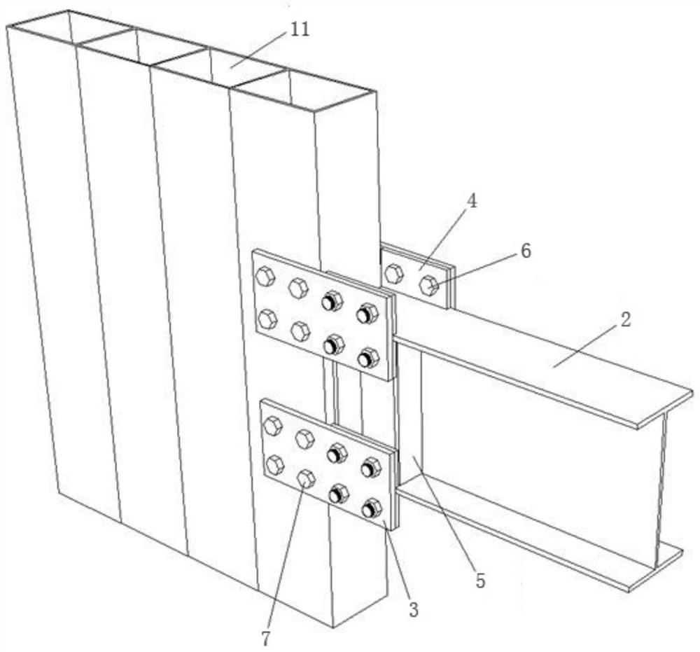
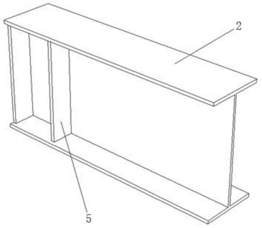
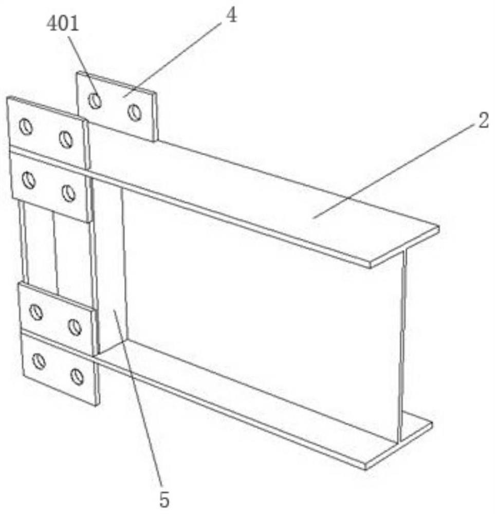
[0029] like Figures 1 to 4 As shown, a steel beam and concrete-filled steel pipe vertical member assembled side plate node includes a steel-filled steel pipe vertical member, a steel beam 2, and a connecting assembly. The two ends of the connection assembly are respectively connected with the composite structural member 11 of the steel pipe bundle and the steel beam 2 .

[0030] Specifically, the steel pipe bundle composite structural member 11 includes a vertically arranged left flange and a right flange, and a plurality of partitions are arranged at intervals between the left flange and the right flange. The steel pipe bundle composite structural member 11 consists of a left flange Edge, right flange and partitions are separated into a plurality of relatively independent units, and the units have cavities, and concrete is poured in the cavities, and the concrete can be ordinary concrete, high-strength concrete, lightweight aggregate concrete or self-com...

Example Embodiment

[0040] Example 2:

[0041] Embodiment 2 is basically the same as Embodiment 1, and its difference is: as Figure 5 As shown, the vertical member of the concrete-filled steel tube concrete is a concrete-filled steel tube column 12, which includes a vertically arranged steel tube with a cavity, and concrete is poured into the cavity.


PUM


Abstract

The invention discloses a fabricated side plate joint of a steel beam and a concrete-filled steel tube vertical element. The joint comprises the concrete-filled steel tube vertical element, the steelbeam and a connecting assembly; the connecting assembly comprises a connecting side plate and a flange welding plate; the flange welding plate is connected with the end, close to the concrete-filled steel tube vertical element, of the steel beam; the end, close to the steel beam, of the connecting side plate is attached to and connected with the side face of the corresponding flange welding plateon the steel beam; and the end, close to the concrete-filled steel tube vertical element, of the connecting side plate is attached to and connected with the side wall of the tail end of the concrete-filled steel tube vertical element. According to the fabricated side plate joint of the steel beam and the concrete-filled steel tube vertical element, on the premise that joint connection is rigid andconnection is safe and reliable, joint on-site welding work is avoided, joint on-site full-bolt connection is achieved, the problems that bolts are difficult to tighten and construction is complex ina closed section are solved, the construction efficiency is remarkably improved, the influence on the environment is small, good anti-seismic performance is achieved, and the steel structure fabricated building technology can be perfected.

Description

technical field [0001] The invention belongs to the technical field of building structure engineering, and in particular relates to an assembled side plate node of a steel beam and a steel pipe concrete vertical member. Background technique [0002] In construction, according to the material of the main structure, there are two commonly used concrete structures and steel structures. The steel tube bundle composite structure shear wall is a new type of lateral force-resisting component that effectively combines the steel structure and the concrete structure, giving full play to the flexible architectural layout of the concrete shear wall, the high degree of industrialization of steel structure production, and the fast construction speed. At the same time, it takes advantage of the material performance advantages of light weight and high strength of steel and high rigidity of concrete. [0003] In the composite shear wall structure system of steel tube bundled concrete, the j...

Claims


Application Information

Patent Timeline
IPC IPC(8): E04B1/38E04B1/58E04C3/04E04C3/34
CPCE04B1/38E04B1/58E04C3/04E04C3/34E04C2003/0452
Inventor 刘宜丰蔡宏昊雷雨张蜀泸邓世斌董博
Owner CHINA SOUTHWEST ARCHITECTURAL DESIGN & RES INST CORP LTD
Why Eureka
Try Eureka