
Fusiform grid and mounting method thereof

An installation method and shuttle-shaped technology, applied in the field of architectural decoration, can solve the problems of affecting the appearance of the full shuttle-shaped decorative part a, unavoidable positioning deviation, long production cycle, etc., achieving considerable economic benefits in production and easy construction and operation , the effect of short production cycle

Pending Publication Date: 2021-03-19
中建五局装饰幕墙有限公司
View PDF0 Cites 0 Cited by
  • Summary
  • Abstract
  • Description
  • Claims
  • Application Information

AI Technical Summary

Problems solved by technology

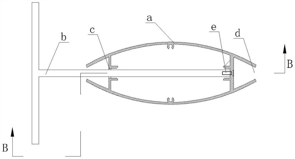
A strip-shaped socket c and a slender strip groove d are provided on the full shuttle-shaped decorative part a, the cost of mold opening is extremely high, the scrap rate is high, and the production cycle is long; during the installation process, the screw e needs to be placed in the slender strip groove d It is not only extremely inconvenient to install directly inside the vertical positioning, but also because the base b has a certain positioning error in the full shuttle-shaped decorative part a, the installation point of the screw e may not necessarily be on the end surface of the base b, and it is difficult to avoid deformation errors. The problem of positioning deviation; after the installation is completed, it is difficult to close the slender groove d, which will affect the external appearance of the full shuttle-shaped decorative part a

Method used


Image

  • Fusiform grid and mounting method thereof
  • Fusiform grid and mounting method thereof
  • Fusiform grid and mounting method thereof

Examples


Embodiment Construction

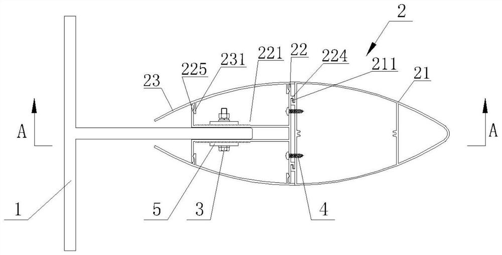
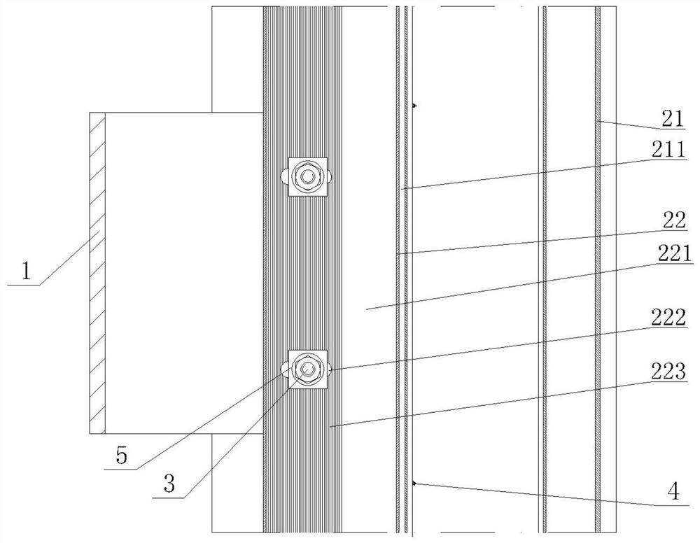
[0031] from figure 1 with figure 2 It can be seen that the shuttle grille of the present invention includes a T-shaped base 1, a shuttle-shaped decorative strip body 2, a bolt assembly 3, a screw 4 and a toothed gasket 5,

[0032] The T-shaped base 1 is fixed on the foundation interface through threaded fasteners, and a round hole is opened on the protruding end of the T-shaped base 1.

[0033] The body 2 of the shuttle-shaped decorative strip includes a half-shuttle housing 21, a connecting piece 22 and two arc-shaped gussets 23, and two symmetrically distributed and side-opened through grooves 221 are arranged at the rear of the connecting piece 22. On the opposite side, there are coaxially arranged elongated holes 222 arranged along the front and back direction of the connector 22,

[0034] The connector 22 is inserted on the protruding end of the T-shaped base 1 through the two-way slot 221, and the bolt assembly 3 passes through the elongated hole 222 and the round ho...


PUM


Abstract

The invention discloses a fusiform grid and a mounting method thereof. The fusiform grille comprises a T-shaped base and a fusiform decoration strip body, the fusiform decoration strip body comprisesa semi-fusiform shell, a connecting piece and two arc-shaped buckle plates, two through grooves which are symmetrically distributed and provided with openings in the side faces are formed in the rearportion of the connecting piece, the extending end of the T-shaped base is arranged between the two through grooves, the T-shaped base and the connecting piece are connected into a whole through boltassemblies, the semi-fusiform shell is detachably connected to the front end of the connecting piece through a buckle and connected into a whole through a screw, the arc-shaped buckle plates are detachably connected to groove openings of the through grooves through buckles, and the front end faces of the two arc-shaped buckle plates are connected with the rear end face of the semi-fusiform shell to form a full-fusiform shape. According to the fusiform grille, an existing integral full-fusiform profile is split into four parts, effective connection of all the parts is completed through mechanical connection of the buckles and the invisible bolt assemblies at the rear ends, and mold opening is easier, construction is more convenient, and the fusiform grille can better adapt to deformation ofstructural errors while the appearance effect is not affected.

Description

technical field [0001] The invention relates to the technical field of architectural decoration, in particular to a shuttle grille and an installation method thereof. Background technique [0002] In recent years, with the continuous development of the construction industry, new buildings, new materials, and new processes at home and abroad have emerged continuously, and the design of building curtain walls has become increasingly diversified, and the manufacturing methods have their own characteristics. more and more. As a novel exterior decoration component, shuttle grille is widely used on the facade of building curtain wall because of its beautiful lines. The decorative parts in the existing shuttle grille are basically divided into two types: 1. semi-fusiform decorative parts (commonly known as bullets); 2. full shuttle-shaped decorative parts. [0003] After long-term use and practice, we found that the above-mentioned shuttle grille decorations have the following pr...

Claims


Application Information

Patent Timeline
Patent Type & Authority Applications(China)
IPC IPC(8): E04B2/88
CPCE04B2/88
Inventor 蒲勇张文龙陈晓娇朱冠辰谭凯任生辉
Owner 中建五局装饰幕墙有限公司
Learn More