
Composite external wall panel for hiding steel frame beam column

A composite exterior wall panel and steel frame technology, applied in the direction of load-bearing elongated structural members, columns, joists, etc., can solve the problems of limited thickness and weight of external wall panels, adverse effects of spatial regularity, etc. Achieve the effect of solving thickness and weight restrictions and convenient construction

Pending Publication Date: 2021-03-19
SOUTH CHINA UNIV OF TECH
View PDF0 Cites 1 Cited by
  • Summary
  • Abstract
  • Description
  • Claims
  • Application Information

AI Technical Summary

Problems solved by technology

[0005] The purpose of the present invention is to overcome the deficiencies of the prior art and provide a composite exterior wall panel for concealing steel frame beams and columns, which solves the adverse effects of steel frame structure beams and columns protruding indoors on the regularity of indoor space, and at the same time due to Type wall design, the floor has a supporting effect on it, which can solve the problem of limited thickness and weight of the external wall panels

Method used


Image

  • Composite external wall panel for hiding steel frame beam column
  • Composite external wall panel for hiding steel frame beam column
  • Composite external wall panel for hiding steel frame beam column

Examples


Embodiment 1

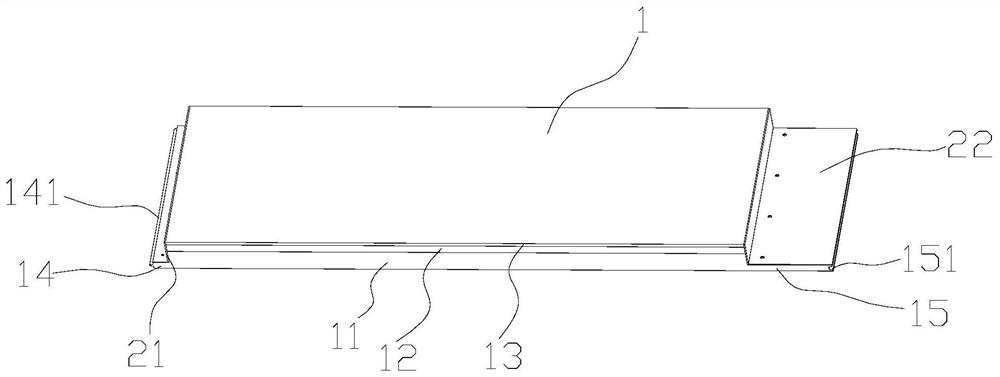
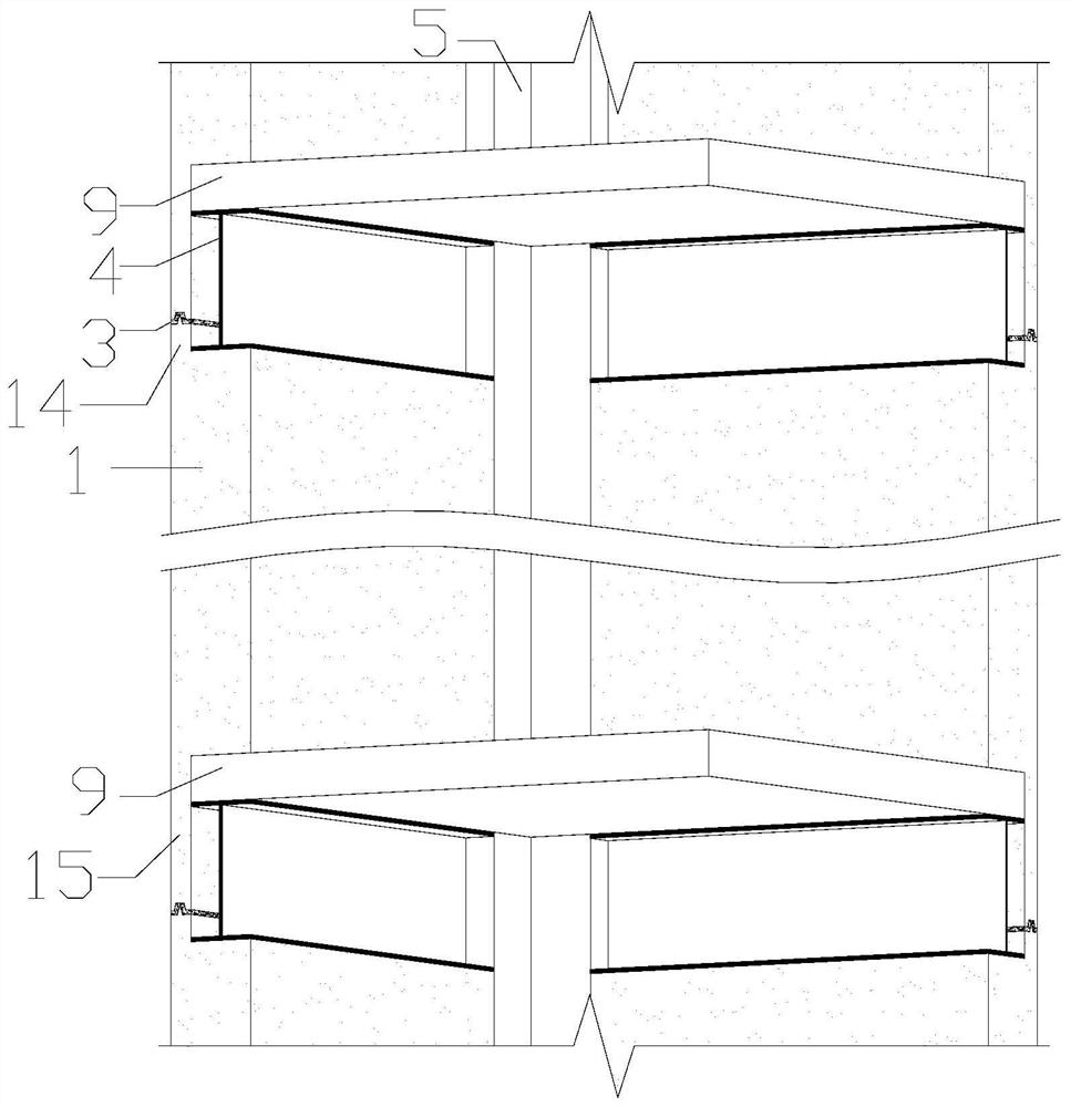
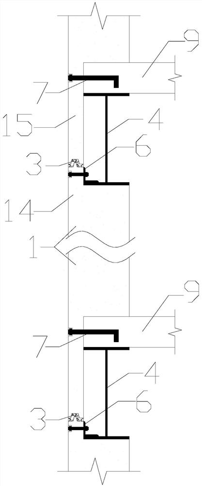
[0027] This embodiment provides a composite exterior wall panel for hiding steel frame beams and columns. The steel frame beams and columns include steel beams 4 and steel columns 5. The steel beams are I-shaped. beam connection.

[0028] The composite exterior wall panel includes the abdomen 1 and the splicing sections located at the upper and lower ends of the abdomen. The section thickness of the abdomen is greater than that of the splicing section. The upper end surface of the abdomen abuts against the bottom surface of the steel beam, and the lower end surface of the abdomen abuts against the top of the lower floor slab The upper and lower adjacent composite exterior wall panels are connected by a splicing section, the inner end surface of the abdomen is flush with the end surfaces of the steel beams and steel columns, the splicing section at the top of the composite exterior wall panel is connected with the steel beam, and the lower end of the composite exterior wall pane...

Embodiment 2

[0035] The difference between this embodiment and embodiment 1 is that, as Figure 4 As shown, the near column end of the abdomen extends vertically from the column end reinforcement section 16, the section thickness of the column end reinforcement section is smaller than the section thickness of the abdomen, the column end reinforcement section fits the side of the steel column, and the column end reinforcement section is preset Multiple bolt holes, multiple bolts 8 are pre-welded on the side of the steel column, the diameter of the bolts can be 10mm, and the spacing can be 300mm, arranged vertically along the steel column, and the bolts on the steel column pass through the bolt holes on the reinforcement section at the end of the column After being connected with the nut, the two sides of the reinforced L-shaped steel plate 23 are respectively connected to the column end reinforcement section and the abdomen, and the reinforced L-shaped steel plate is provided with bolt holes...


PUM


Abstract

The invention discloses a composite external wall panel for hiding a steel frame beam column. The steel frame beam column comprises a steel beam and a steel column, the steel beam is I-shaped, the upper end of the steel beam supports a floor, and the steel column is connected with the steel beam. The composite external wall panel comprises a web and splicing sections located at the upper end and the lower end of the web, and the section thickness of the web is greater than that of the splicing sections. The upper end face of the web abuts against the bottom face of the steel beam, the lower end face of the web abuts against the top face of the lower-layer floor, every two vertically-adjacent composite outer wall panels are connected through the splicing sections, the inner end face of theweb is flush with the end face of the steel beam and the end face of the steel column, the splicing sections at the upper ends of the composite outer wall panels are connected with the steel beam, andthe splicing sections at the lower ends of the composite external wall panels are connected with the lower-layer floor. The composite external wall panel for hiding the steel frame beam column completely covers the steel beam and the steel column which protrude out of a room, the problems that the beam column protruding out of the room has an adverse effect on the indoor space regularity, meanwhile, the thickness and the weight of an externally-hung wall panel are limited due to the semi-embedded wall design and the floor having a supporting effect on the composite external wall panel are solved.

Description

technical field [0001] The invention relates to the technical field of building components, in particular to a composite exterior wall panel for hiding steel frame beams and columns. Background technique [0002] In recent years, prefabricated buildings have been vigorously promoted, and research on prefabricated building structures has always been a hot topic, including research on prefabricated components, research on connection structures, and research on overall performance. Improving and perfecting the prefabricated building structure technology is the key to promoting the industrialization of construction and residential construction. [0003] The light steel frame structure itself has the characteristics of simple prefabricated building construction, convenient disassembly and assembly, and flexible layout. Perfecting the prefabricated steel structure construction system, realizing component prefabrication and on-site installation, will improve the speed and quality o...

Claims


Application Information

Patent Timeline
Patent Type & Authority Applications(China)
IPC IPC(8): E04C2/288E04C2/30E04B1/61E04B1/38E04C3/04E04C3/32E04B1/41E04B1/66
CPCE04C2/288E04C2/30E04B1/6137E04B1/38E04C3/04E04C3/32E04B1/41E04B1/66E04C2003/0452
Inventor 姜正荣黄瑞聪邱俊明蔡健石开荣陈庆军左志亮
Owner SOUTH CHINA UNIV OF TECH
Learn More