A cryogenic liquid fuel geyser restraint pipeline

A low-temperature liquid and pipeline technology, which is applied in the field of low-temperature liquid fuel geyser suppression pipelines, can solve the problems of increased overall weight of pipelines, waste of low-temperature liquid, and complex process of the system, and achieve the effect of reducing operation and maintenance costs and reducing weight

Active Publication Date: 2021-09-03
XI AN JIAOTONG UNIV
View PDF6 Cites 0 Cited by
  • Summary
  • Abstract
  • Description
  • Claims
  • Application Information

AI Technical Summary

Problems solved by technology

[0004] According to the above-mentioned geyser generation and suppression mechanism, in engineering practice, for example, in the main delivery system of rocket cryogenic fuel, an additional circulation return pipeline is added and supplemented by helium injection to make the gap between the main delivery pipeline and the return pipe The circulating flow of the fluid is used to suppress the geyser; the system process of this suppression scheme is extremely complicated, and due to the introduction of additional auxiliary equipment, the weight of the rocket is significantly increased, thereby reducing the payload of the rocket
The Chinese utility model patent with the publication number 205479929U discloses "Installation structure for low-temperature liquid transport wear-resistant pipeline". This structure adds a concentric circular tube to the main liquid transport pipeline to generate fluid circulation to suppress geysers. Similarly, due to the introduction of concentric pipes, the overall weight of the pipe increases, and at the same time, the flow resistance of the fluid in the pipe increases, resulting in additional energy consumption
Another geyser suppression scheme is to continuously inject low-temperature liquid at the bottom of the main pipeline to maintain the flow state of the fluid in the pipeline; this scheme requires continuous injection of low-temperature fluid, which on the one hand causes waste of low-temperature liquid, and on the other hand On the one hand, it is not conducive to long-term operation and maintenance

Method used


Image

  • A cryogenic liquid fuel geyser restraint pipeline
  • A cryogenic liquid fuel geyser restraint pipeline
  • A cryogenic liquid fuel geyser restraint pipeline

Examples


Embodiment Construction

[0021] The present invention will be described in detail below in conjunction with the accompanying drawings and embodiments.

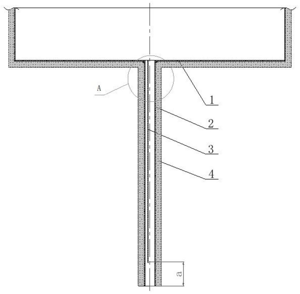
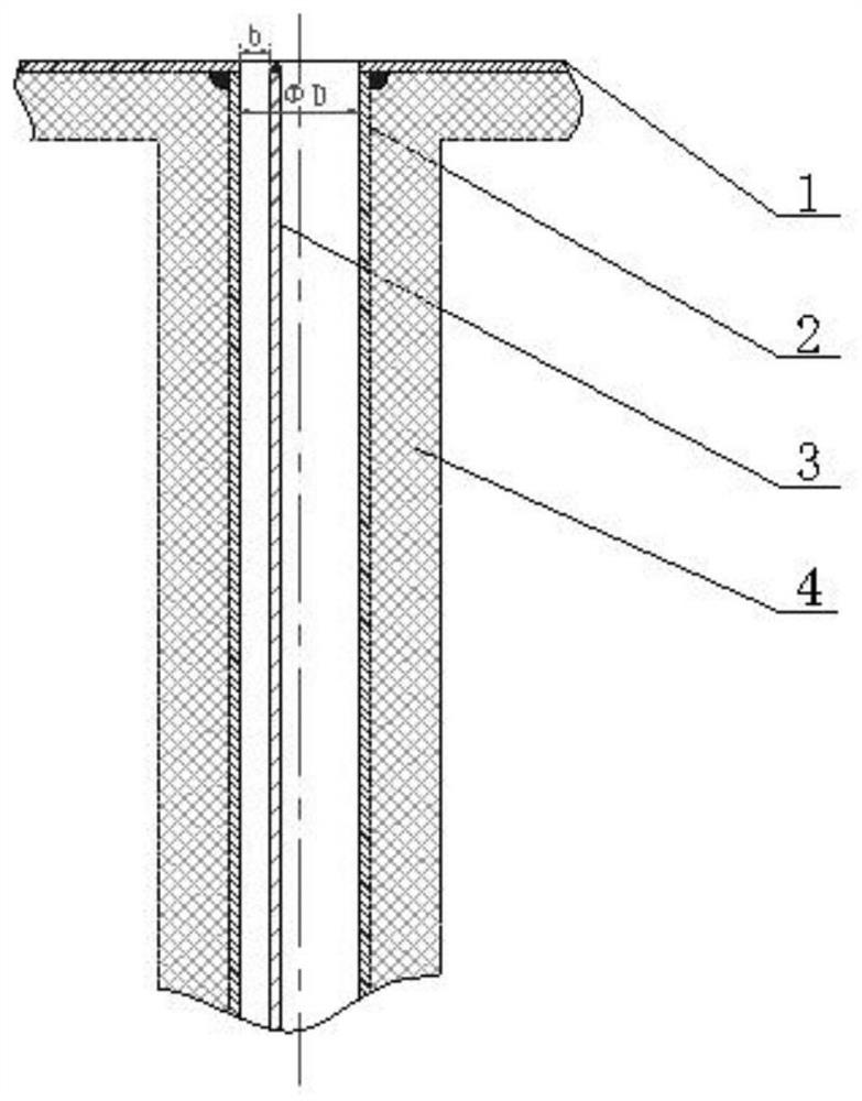
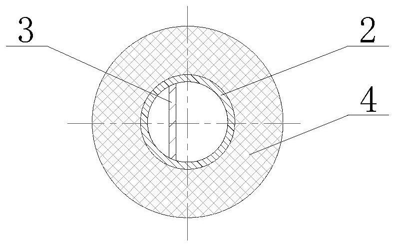
[0022] refer to figure 1 , figure 2 and image 3 , a low-temperature liquid fuel geyser suppression pipeline, comprising a main pipeline 2 welded below a low-temperature liquid fuel storage tank 1, the outer side of the main pipeline 2 is provided with a heat insulating layer 4, and the heat insulating layer 4 is evenly coated on the outer surface of the main pipeline 2, It is used to block the heat leakage of the environment; the main pipeline 2 is provided with a backflow baffle 3 inside, and the backflow baffle 3 is welded with the main pipeline 2 to ensure that the backflow baffle 3 is in the eccentric position of the main pipeline 2, and at the same time, the length of the backflow baffle 3 is less than The total length of the main pipe 2 ensures that the bottom of the main pipe 2 leaves a gap for liquid backflow.

[0023] The low-temperature...


PUM


Abstract

A low-temperature liquid fuel geyser suppression pipeline, including a main pipeline connected to the lower part of the low-temperature liquid fuel storage tank, an insulating layer is provided outside the main pipeline, and a backflow baffle is arranged inside the main pipeline, and the backflow baffle is connected with the main pipeline to ensure The backflow baffle is located at the eccentric position of the main pipeline, and at the same time, the length of the backflow baffle is shorter than the total length of the main pipeline, ensuring that the liquid backflow gap is left at the bottom of the main pipeline; Ability to achieve the suppression effect on geysers; it has the characteristics of simple structure, light weight, easy process, safety and reliability, which greatly reduces the weight of additional equipment introduced to suppress geysers, and reduces equipment operation and maintenance costs.

Description

technical field [0001] The invention belongs to the technical field of fluid delivery pipelines, in particular to a low-temperature liquid fuel geyser suppression pipeline. Background technique [0002] Cryogenic liquid fuels (liquid hydrogen, liquid oxygen, liquefied natural gas) have excellent properties of non-toxic, non-polluting and high specific impulse, and are widely used in the fields of industrial energy and aerospace propulsion. Due to the low boiling point and small latent heat of low-temperature fuel, under the action of environmental heat leakage, two-phase flow phenomenon will inevitably appear in the pipeline of low-temperature fuel, which will have an adverse effect on the stable transportation of fluid; more seriously, in a long In the vertical pipeline, the bubbles generated by the boiling of the liquid cannot be discharged in time, which may cause geysers in the pipeline. During the geyser process, the gas-liquid mixture in the pipeline gushes at high sp...

Claims


Application Information

Patent Timeline
Patent Type & Authority Patents(China)
IPC IPC(8): F17C13/00F16L9/19F16L9/02F16L59/14F16L59/08F16L59/02F16L59/065
CPCF16L9/02F16L9/19F16L59/029F16L59/065F16L59/08F16L59/14F17C13/00F17C2221/011F17C2221/012F17C2221/033F17C2223/0153F17C2223/0161Y02E60/32
Inventor 厉彦忠毛红威王磊谢福寿黄晓宁夏斯琦
Owner XI AN JIAOTONG UNIV
Why Eureka
Try Eureka