Patch pressurizing device and method for sensor

A pressurizing device and sensor technology, applied in the field of sensors, can solve problems such as low qualification rate and uneven pressurization force, and achieve the effect of improving productivity

Active Publication Date: 2021-03-19
ZHONGHANG ELECTRONICS MEASURING INSTR
View PDF7 Cites 0 Cited by
  • Summary
  • Abstract
  • Description
  • Claims
  • Application Information

AI Technical Summary

Problems solved by technology

[0006] In order to solve the problems existing in the prior art, the present invention provides a patch pressure device and method for sensors, which solves the uneven pressure of the traditional patch, The problem of low pass rate is caused by the simple structure, which can ensure the uniformity of the pressure and improve the product yield

Method used


Image

  • Patch pressurizing device and method for sensor
  • Patch pressurizing device and method for sensor
  • Patch pressurizing device and method for sensor

Examples


Embodiment 1

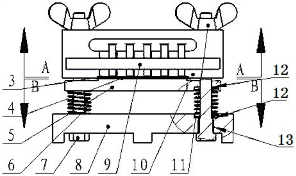
[0039] A patch pressure device for a sensor, comprising a positioning plate 10, a polytetrafluoroethylene plastic film 3, a pressure transmission plate 4, a spring 6, a fixed base 8, a guide rod 7, a nut 11, a buffer pad 4 and an adhesive tape 9. When in use, tighten the guide rod 7 on the fixed base 8, and place the spring 6, the pressure transmission plate, the buffer pad 4, the polytetrafluoroethylene film 3, and the positioning plate upwards in sequence according to the assembly relationship. The sensor 1 that has been pasted has been placed on the positioning plate. 10), the nut parts, then apply the rated pressurization force, after the pressurization is completed, lock the nut 11, and finally remove the rated pressurization force, the patch area 15 of the sensor 1 can be completed for patch pressurization.

[0040] The parts of the fixed base 8 include a threaded hole 13 for fixing the guide rod 7, and a step hole for placing the spring 6 concentrically with the threaded...

Embodiment 2

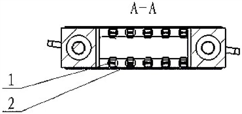
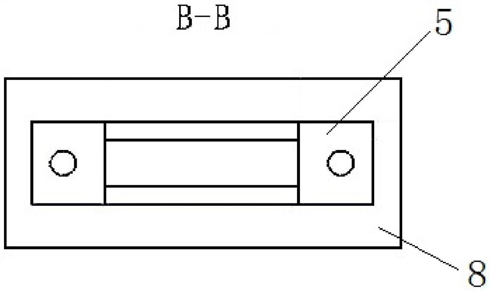
[0051] In order to solve the problem that the sensor is not easy to locate in the pressurization process of the micro-sensor patch, and the patch pressure is uneven, resulting in uneven adhesive layer after curing, air bubbles, and low process qualification rate caused by lack of glue, the present invention provides a sensor. Tablet pressing device, such as figure 1 , figure 2 with image 3 As shown, as a specific embodiment of the present invention, a sensor patch pressing device includes a pressure transmission plate 5 , a high temperature compression spring 6 , a guide rod 7 , a fixed base 8 , a positioning plate 10 and a wing nut 11 . The lower end of the guide rod 7 is threaded, and is screwed into the threaded hole 13 on the fixing seat 8, thereby establishing the guide rod reference;

[0052] A spring 6 is placed on the guide rod 7, the lower end of the spring 6 is placed in the spring counterbore 12 on the fixed base 7, the upper end of the spring 6 is in contact wi...


PUM


Abstract

The invention discloses a patch pressurizing device and method for a sensor. The device comprises a pressure transmission plate, a spring, a guide rod, a fixed base, a positioning plate and a nut, a threaded hole is formed in the fixed base, through holes are formed in the pressure transmission plate and the positioning plate, and the guide rod sequentially penetrates through the threaded hole ofthe fixed base, the through hole of the pressure transmission plate and the through hole of the positioning plate and is fixed by the nut; a patch area of the sensor is clamped between the pressure transmission plate and the positioning plate; and the spring is arranged between the pressure transmission plate and the fixed base. The method comprises the following steps: step 1, fixing the sensor on the positioning plate, and fixing the patch area of the sensor on the pressurizing surface of the positioning plate; 2, screwing the guide rod in the threaded hole in the fixed base, and sequentially arranging the spring, the pressure transmission plate, the positioning plate and the nut on the guide rod to be fixed; and 3, compressing the patch pressurizing spring, generating a gap between thenut and the upper surface of the positioning plate, and tightening the nut to perform pressurizing compensation after the pressurizing force value is stable.

Description

technical field [0001] The invention belongs to the technical field of sensors, in particular to a patch pressing device and method for sensors. Background technique [0002] The chip pressurization process is a key step in the sensor manufacturing process. Before the resistance strain gauge is solidified on the elastic body through the patch glue, the strain gauge needs to be accurately pasted on the strain area of ​​the elastic body to be collected, and a uniform and stable adhesive layer is formed through the patch pressing device, and the adhesive layer is guaranteed to be free from damage. Bubbles, bulges, lack of glue, etc. Therefore, the pros and cons of the patch pressing device will directly affect the position accuracy and sticking quality of the strain gauge patch, and ultimately affect the test performance of the sensor. [0003] In the conventional patch pressurization device, the pressure is maintained only by the pre-tightening force between the bolt and the...

Claims


Application Information

Patent Timeline
Patent Type & Authority Applications(China)
IPC IPC(8): G01B7/16
CPCG01B7/18
Inventor 晏志鹏赵恒张勋花肖航高艳霞吴梅雒平华王宁
Owner ZHONGHANG ELECTRONICS MEASURING INSTR
Why Eureka
Try Eureka