
Self-powered deformation monitoring and transmission integrated device

A technology of deformation monitoring and self-power supply, which is applied in electromagnetic measuring devices, electric/magnetic solid deformation measurement, signal transmission systems, etc. It can solve problems such as complex wiring work, hidden dangers of deformation, limited fixed positions, etc., and achieves expanded usage scenarios, Improved safety and less prone to damage

Pending Publication Date: 2021-03-19
TSINGHUA UNIV +1
View PDF0 Cites 0 Cited by
  • Summary
  • Abstract
  • Description
  • Claims
  • Application Information

AI Technical Summary

Problems solved by technology

At the same time, scenes such as slopes and fields also have possible deformation safety hazards in complex and extreme environments, which have extremely high application requirements for remote monitoring.
[0003] However, the current deformation monitoring module often requires additional power supply, which limits the usage scenarios
At the same time, its complicated wiring work is time-consuming and prone to problems such as poor contact of wires, which affects the normal use of measuring equipment
In addition, the measurement and installation conditions of roofs and slopes are complicated, the fixed positions are limited, the device is exposed to the external environment, and open fire construction may not be possible, and it is necessary to avoid the influence of rainwater, and set up convenient and fast equipment maintenance methods. At present, there is a lack of mature devices to meet the needs of roofs These requirements of the deformation monitoring module

Method used


Image

  • Self-powered deformation monitoring and transmission integrated device
  • Self-powered deformation monitoring and transmission integrated device
  • Self-powered deformation monitoring and transmission integrated device

Examples


Embodiment Construction

[0066] Embodiments of the present invention are described in detail below, examples of which are shown in the drawings, wherein the same or similar reference numerals designate the same or similar elements or elements having the same or similar functions throughout. The embodiments described below by referring to the figures are exemplary only for explaining the present invention and should not be construed as limiting the present invention.

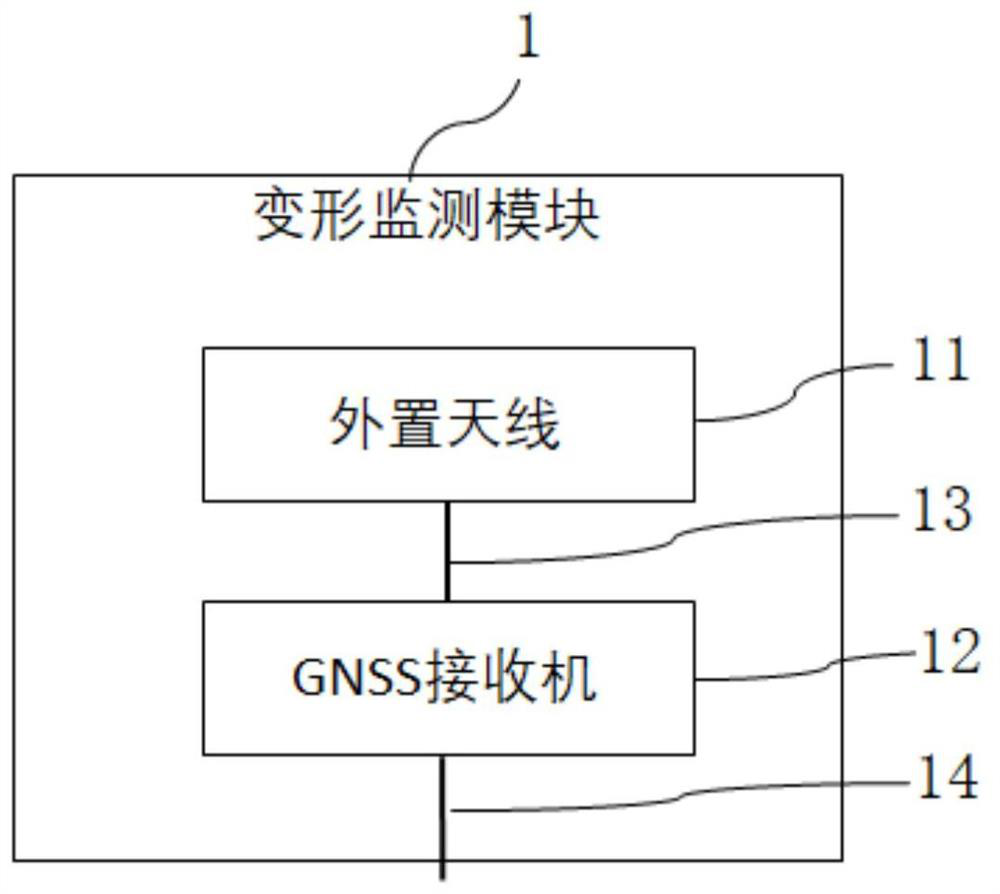
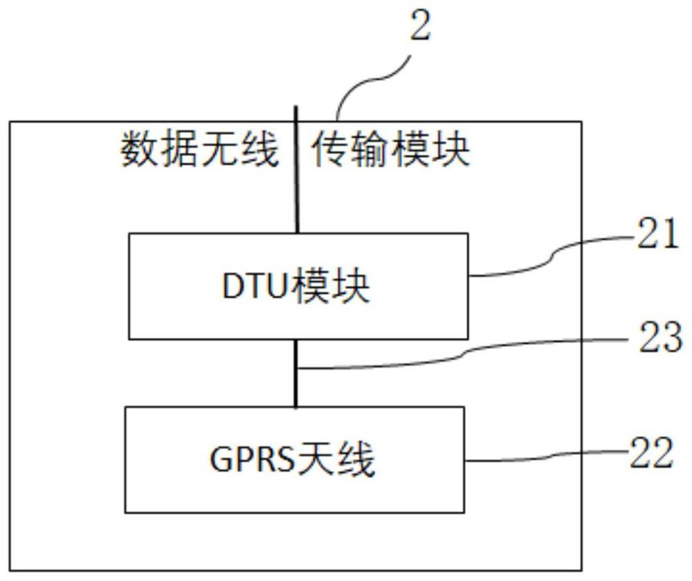
[0067] Combine below Figure 1 to Figure 9 The self-powered integrated deformation monitoring and transmission device 1000 of the embodiment of the present invention will be described.

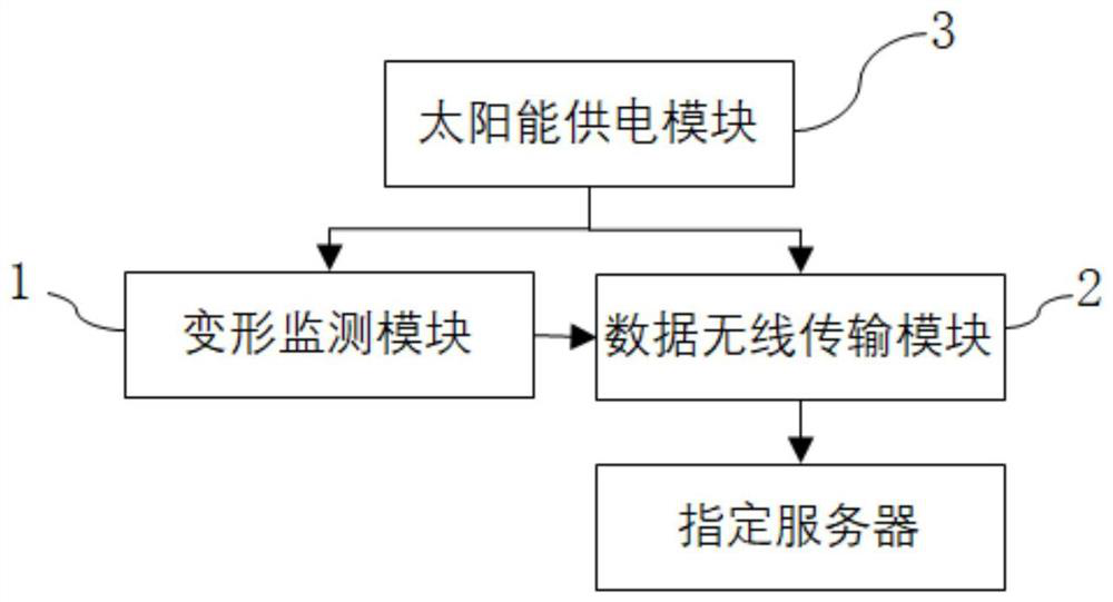
[0068] Such as figure 1 , image 3 and Figure 5 As shown, the self-powered integrated deformation monitoring and transmission device 1000 according to the embodiment of the present invention includes a deformation monitoring module 1 , a wireless data transmission module 2 , a solar power supply module 3 and an external support and protection module ...


PUM


Abstract

The invention discloses a self-powered deformation monitoring and transmission integrated device. The device comprises a deformation monitoring module, a data wireless transmission module, a solar power supply module and an external support protection module; the deformation monitoring module is used for carrying out health monitoring on a large building structure to obtain required deformation monitoring data; the data wireless transmission module is used for receiving the deformation monitoring data of the deformation monitoring module and transmitting the deformation monitoring data to a specified server; the solar power supply module comprises a solar panel and a power supply unit, the solar panel is used for converting solar energy into electric energy and transmitting the electric energy to the power supply unit, and the power supply unit is used for supplying power to the deformation monitoring module and the data transmission module; the deformation monitoring module, the datawireless transmission module and the power supply unit are installed in the external support protection module. According to the invention, the use scene is expanded, the installation is simple, the roof space is not occupied, more damage to the overall modeling appearance of a building is not caused, and the use safety is high.

Description

technical field [0001] The invention relates to the technical field of engineering measuring devices, in particular to a self-powered integrated deformation monitoring and transmission device. Background technique [0002] The long-span space structure has been widely used in large-scale structures such as stadiums and airports. This structural system provides more space for the interior design of buildings, and has been favored by more and more architectural designers. However, due to the aging of materials, accidental damage and sudden dynamic response, and the importance of such buildings is often high, the structure faces greater safety hazards. It is of great significance to use the layout roof deformation monitoring module to monitor the health of long-span spatial structures and to give early warning of possible safety hazards. At the same time, scenes such as slopes and fields also have possible deformation safety hazards in complex and extreme environments, which h...

Claims


Application Information

Patent Timeline
Patent Type & Authority Applications(China)
IPC IPC(8): G01B7/16G08C17/02
CPCG01B7/16G08C17/02
Inventor 冯鹏李少华张道博罗惠平谢崇峰刘天桥苏振华苏李渊
Owner TSINGHUA UNIV
Learn More