Imaging view field splicing structure

A field of view splicing and imaging technology, which is applied in measurement devices, instruments, scientific instruments, etc., can solve the problems of heavy overall mechanism and complex splicing layout of spectrometers.

Inactive Publication Date: 2021-03-19
AEROSPACE INFORMATION RES INST CAS
View PDF3 Cites 0 Cited by
  • Summary
  • Abstract
  • Description
  • Claims
  • Application Information

AI Technical Summary

Problems solved by technology

[0005] The field of view stitching technology of spectrometers in the prior art is difficult to meet the field of view stitching of spectrometers with different bands, and the overall structure is heavy, and the layout of various spectrometers is complicated

Method used


Image

  • Imaging view field splicing structure
  • Imaging view field splicing structure

Examples


specific Embodiment approach

[0015] The structure of the splicing of the imaging field of view of the present invention, its preferred embodiment is:

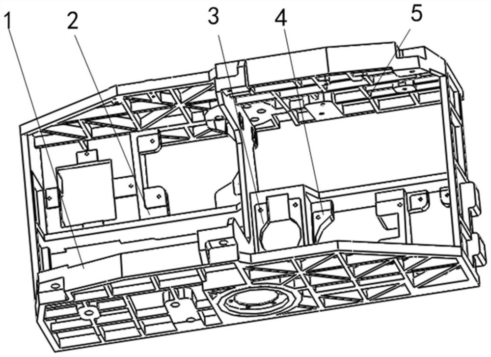
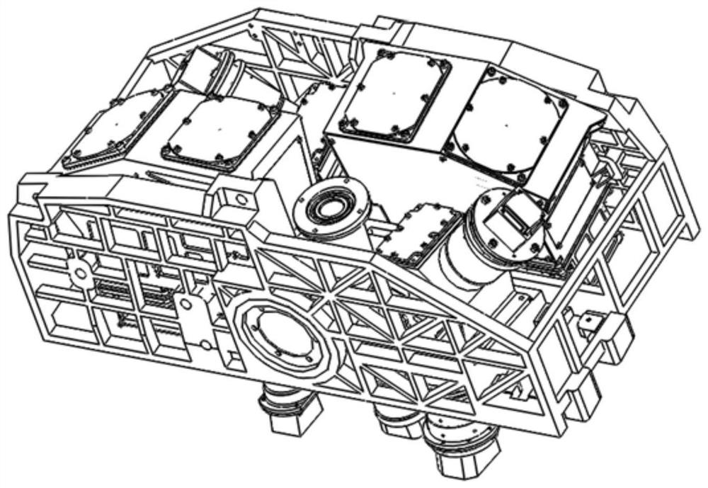
[0016] It includes the installation flange surface of two infrared spectrometers and the installation flange surface of three visible spectrometers, so as to realize the installation splicing of two infrared spectrometers and three visible spectrometers.

[0017] The splicing angle of the field of view of the two infrared spectrometers is 20°, and the splicing structure of the inner figure of eight is adopted. The angle between the mounting flange of each infrared spectrometer and the ground is 10°;

[0018] The splicing angle of field of view of the three visible spectrometers is 19°. One of the visible spectrometers is a compensation spectrometer, and its mounting flange is parallel to the ground. The angle between the mounting flanges of the other two visible spectrometers is 9.5°. .

[0019] The material of the structure is ZL105.

[0020] The struct...

specific Embodiment

[0027] Such as figure 1 , figure 2 As shown, the field of view of the infrared spectrometer is 20°, and the shape of the inner eight is adopted, and the angle between each flange surface and the ground is 10°. The field of view of the visible spectrometer is spliced ​​at 19°, and the spectrometer at flange surface 3 is a compensation spectrometer to ensure that the splicing field of view of the other two spectrometers is complete, so it is designed to be parallel to the ground, and the spectrometers on flange surfaces 2 and 4 use The angles to the ground are 9.5°, and the splicing of three spectrometers ensures the integrity of the splicing of the large field of view.

[0028] Specific implementation steps:

[0029] 1) Material selection:

[0030] The material selection of this structure mainly considers the strength and processing stability. Considering the overall weight, the material selection is ZL105. L105 has good casting performance and high air tightness, good mac...


PUM


Abstract

The invention discloses an imaging view field splicing structure which comprises mounting flange surfaces of two infrared spectrometers and mounting flange surfaces of three visible spectrometers, andrealizes mounting and splicing of the two infrared spectrometers and the three visible spectrometers. The view field splicing angle of the two infrared spectrometers is 20 degrees, an inner splayed splicing structure is adopted, and the included angle between the mounting flange surface of each infrared spectrometer and the ground is 10 degrees; the field splicing angle of the three visible spectrometers is 19 degrees, one visible spectrometer is a compensation spectrometer, the mounting flange surface of the visible spectrometer is parallel to the ground, and the included angles between themounting flange surfaces of the other two visible spectrometers and the ground are 9.5 degrees respectively. According to the structure, a frame type casting structure is adopted, under the conditionthat the design requirements for high lightness and light weight of airborne design are met, splicing of wide view fields of spectrometers is met, and it is also guaranteed that the whole equipment meets the design requirements for visible-to-short-wave infrared imaging through carrying of imaging spectrometers of different spectral bands.

Description

technical field [0001] The invention relates to an optical-mechanical design technology, in particular to a structure for splicing imaging fields of view. Background technique [0002] In modern warfare, effective information acquisition becomes the premise and basis for decisive victory. A single imaging spectrometer has a limited field of view and cannot meet many practical needs. [0003] In the application of aerial remote sensing information acquisition, the aircraft is the main carrying platform, and it is gradually developing towards the intelligentization of drones. Among many aerial remote sensing information acquisition methods, ordinary cameras can be used to obtain two-dimensional images of targets to understand the spatial image information of targets; spectrometers can be used to obtain target spectral curves to study the physical and chemical characteristics of targets; With the emergence of technology, the combination of the camera and the spectroscopic ins...

Claims


Application Information

Patent Timeline
Patent Type & Authority Applications(China)
IPC IPC(8): G01J3/28G01J3/02
CPCG01J3/2823G01J3/0202G01J3/0278G01J3/0291
Inventor 何晓英周锦松冯蕾魏立冬李雅灿景娟娟聂博洋徐丽杨雷
Owner AEROSPACE INFORMATION RES INST CAS
Why Eureka
Try Eureka