Electrolytic cell fault detection system and method

A fault detection and electrolytic cell technology, which is applied in electrolytic process, electrolytic components, radiation pyrometry, etc., can solve the problems of low efficiency of manual detection of electrolytic cell, achieve the effect of reducing detection cost, expanding detection angle of view, and improving positioning accuracy

Pending Publication Date: 2021-03-19
湖南傲英创视信息科技有限公司
View PDF0 Cites 2 Cited by
  • Summary
  • Abstract
  • Description
  • Claims
  • Application Information

AI Technical Summary

Problems solved by technology

[0004] The invention provides an electrolytic cell fault detection system and method, which are used to solve the technical problem that the efficiency of the existing manual detection method for the electrolytic cell is not high

Method used


Image

  • Electrolytic cell fault detection system and method
  • Electrolytic cell fault detection system and method
  • Electrolytic cell fault detection system and method

Examples


Embodiment 1

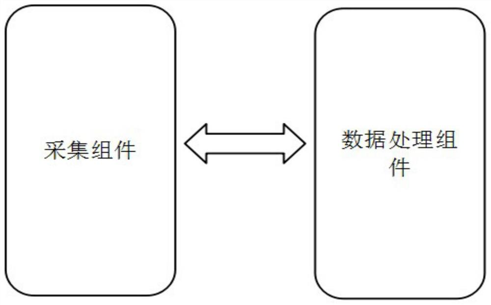
[0050] Such as figure 1 As shown, the present invention discloses an electrolytic cell fault detection system, including: an acquisition component and a data processing component connected to the acquisition component, the acquisition component is used to obtain the infrared thermal image of the electrolytic cell in real time, and send the infrared thermal image to the data Processing components;

[0051] The data processing component is used to receive and extract the boundary contour and specification information of the electrolytic cell from the infrared thermal image, find the position of the electrode plate of the electrolytic cell according to the specification information, and determine the position of each electrode plate in the infrared The position on the thermal image; based on the position of each polar plate on the infrared thermal image, the average brightness of each polar plate on the infrared thermal image is counted, and the average brightness of each polar p...

Embodiment 2

[0058] The second embodiment is an extended embodiment of the embodiment, and its difference from the first embodiment is that the structure and function of the electrolyzer fault detection system are refined, including the following:

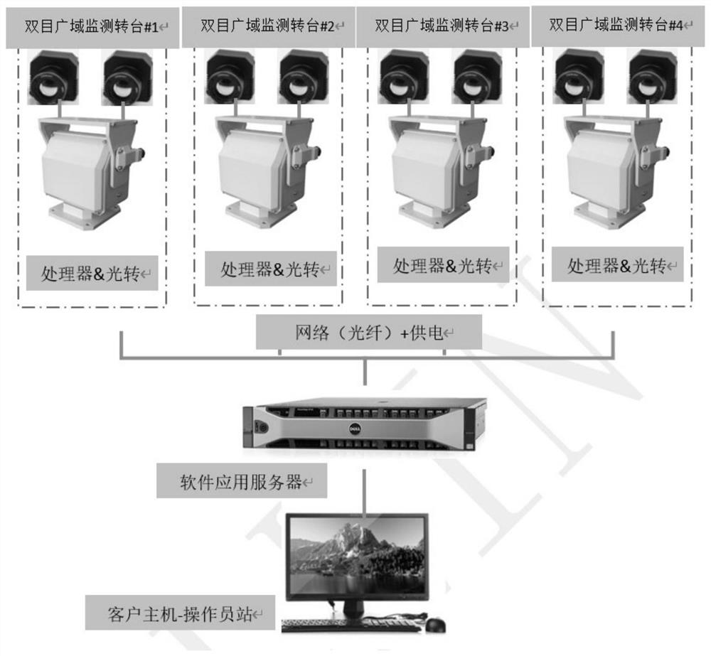
[0059] In this example, if figure 2 As shown, an electrolytic cell fault detection system is disclosed, including multiple sets of acquisition components (ie, the binocular wide-area monitoring turntable in the figure), a data processing component connected to multiple sets of acquisition components, and a client host connected to the data processing components end;

[0060] Among them, the acquisition component includes a precision turntable with horizontal pitch adjustment, a processor, and a binocular infrared detector with a short-focus infrared camera and a long-focus infrared camera fixed on the precision turntable through an optical load platform. The detectors are connected with the data processing components through the processor;

...


PUM


Abstract

The invention discloses an electrolytic cell fault detection system and method. The method comprises the steps of: acquiring and extracting the boundary contour and specification information of an electrolytic cell in real time from an infrared thermal image of the electrolytic cell; searching the polar plate position of the electrolytic cell according to the specification information, and determining the position of each polar plate of the electrolytic cell in the infrared thermal image according to the polar plate position and the boundary contour of the electrolytic cell; based on the position of each polar plate in the infrared thermal image, counting the average brightness of each polar plate in the infrared thermal image, comparing the average brightness of each polar plate with a preset brightness threshold value respectively, and judging whether each polar plate breaks down or not according to the comparison result, thus rapidly detecting whether faults exist in the polar plates in the electrolytic cell, and positioning the failed polar plate.

Description

technical field [0001] The invention relates to the technical field of electrolytic cell fault detection, in particular to an electrolytic cell fault detection system and method. Background technique [0002] ISA (permanent cathodic electrolysis, also known as ISA) electrolysis method is a modern and popular copper electrolytic purification method. Its characteristic is that the cathode is a permanent stainless steel plate, and electrolytic copper is deposited on the stainless steel cathode plate, and then taken out and peeled off periodically as a finished product. The stainless steel cathode is straight and the cathode is of high quality. [0003] The existing ISA (permanent cathodic electrolysis, also known as ISA) electrolysis method needs to place as many pairs of plates as possible in an electrolytic cell with a certain size in order to ensure the total daily production and reduce power consumption, but for the sake of production safety Taking into account, usually t...

Claims


Application Information

Patent Timeline
Patent Type & Authority Applications(China)
IPC IPC(8): G01R31/52G01B11/24G01J5/00C25C7/06C25C1/12
CPCC25C1/12C25C7/06G01B11/24G01J5/00G01J2005/0077G01R31/52Y02P10/20
Inventor 吴海根陈小天贺遵亮黄营磊邱程李阳秦江山朱乔贺伟刘申耀
Owner 湖南傲英创视信息科技有限公司
Why Eureka
Try Eureka