Bullet firing counting device based on recoil force detection

A technology of counting device and recoil force, applied in the direction of counting mechanism/item, weapon accessories, instruments, etc., can solve the problems of unpublished statistics of the number of bullets fired by firearms and the time of firing bullets by firearms. Simple, easy to disassemble, small size

Pending Publication Date: 2021-03-19
济南瑞特安防设备有限公司
View PDF3 Cites 0 Cited by
  • Summary
  • Abstract
  • Description
  • Claims
  • Application Information

AI Technical Summary

Problems solved by technology

[0006] Although the projectile information mentioned in this invention includes at least one of the following information: the number of times the firearm fires bullets and the time when the firearm fires bullets, it does not disclose the specific structure and principle of counting the number of times the firearm fires bullets and the time when the firearm fires bullets
[0007] The prior art lacks a bullet firing counting device that is convenient for disassembly and assembly, does not change the original structure of the firearm, and detects and counts more accurately

Method used


Image

  • Bullet firing counting device based on recoil force detection
  • Bullet firing counting device based on recoil force detection
  • Bullet firing counting device based on recoil force detection

Examples


Embodiment approach 1

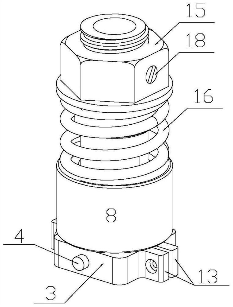
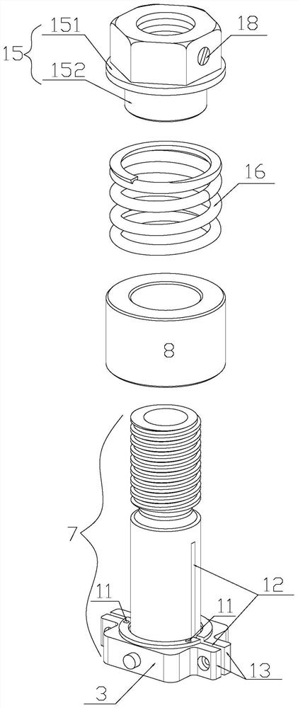
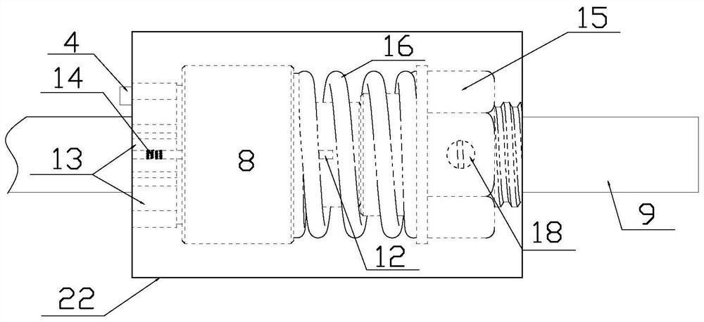
[0030] Implementation mode one: if Figure 1-6 As shown, the bullet firing counting device based on recoil detection includes a single-chip microcomputer 1, a wireless transmitter 2 connected to the output of the single-chip microcomputer 1, a power switch 4 arranged on the surface of the base 3, a display device 5, and a display device 5 that is connected to and connected to the display device 5. The wireless receiving device 6 matched with the wireless transmitting device 2 is characterized in that: it includes a base tube 7, an annular inertial metal slider 8 and a casing 22, and the inner diameter of the base tube 7 is equal to that of the gun barrel 9 of a firearm. Outer diameter, the base 3 is fixed on one end of the base tube 7, the single-chip microcomputer 1 is provided with an open circuit counting module 10, and the annular inertial metal slider 8 is sleeved on the base tube 7 and can slide on the base tube 7 , the base 3 is provided with two contacts 11 facing the ...

Embodiment approach 2

[0035] Implementation mode two: if Figure 7-8 As shown, the corresponding position of the base 3 is fixed with a ferromagnetic plate 20, and the annular inertial metal slider 8 includes a contact surface ring 81, an externally threaded pipe 82 and a permanent magnet ring 83, and the contact surface ring 81 is fixedly connected At the rear end of the externally threaded pipe 82, the center of the permanent magnet ring 83 has an internally threaded hole, which is matched with the external thread on the externally threaded pipe 82, and the contact surface ring 81 of the annular inertial metal slider 8 It can be contacted or separated from the contact 11. The front part of the base pipe 7 is provided with an external thread, and an anti-loosening nut 21 is screwed on it. Except for the ferromagnetic plate 20 and the permanent magnetic ring 83, the base pipe 7, anti-off Other parts in the nut 21, the base 3 and the base 3 are all made of non-ferromagnetic material, and the permane...


PUM


Abstract

The invention relates to a bullet firing counting device based on recoil force detection. In order to fill up the blank of the prior art, the device comprises a single-chip microcomputer, a wireless transmitting device, a base, a power switch, a display device, a wireless receiving device, a base tube and an annular inertia metal sliding block, the annular inertia metal sliding block is arranged on the base tube in a sleeving mode and can slide, and two contacts are arranged on the base. The contacts and the annular inertia metal sliding block are jointly connected with the open circuit counting module in series to form a counting loop, recoil force generated every time a matched gun shoots a bullet enables the matched gun, the base tube and other components except the annular inertia metal sliding block on the base tube to retreat integrally, the annular inertia metal sliding block is affected by inertia. The annular inertia metal sliding block is separated from the contact, the counting loop is disconnected, and the disconnection counting module in the single-chip microcomputer counts once and finally displays the result on the display device. The invention is suitable for bulletfiring statistics of gun using units such as military police in the shooting training process.

Description

technical field [0001] The invention relates to a bullet firing counting device based on recoil force detection. Background technique [0002] The Chinese invention patent authorized on December 2, 2009 with the authorization announcement number CN 100565083 C discloses a counting device, which relates to a device (12) for counting bullets fired by an automatic firearm (11), including accommodating Cartridge cavity for cartridges that can be discharged through the discharge window. The inventive device comprises first firing means emitting a continuous electromagnetic signal such that the cartridge housing corresponding to the ejection of the used cartridge from the cartridge chamber interrupts said electromagnetic signal. The bullet counting device (12) of the present invention can monitor the number of cartridge shells discharged from the cartridge cavity of the firearm (11) through the aforementioned discharge window and can still be installed in the cartridge case (13) ...

Claims


Application Information

Patent Timeline
Patent Type & Authority Applications(China)
IPC IPC(8): G06M1/10F41A33/00
CPCF41A33/00G06M1/102
Inventor 赵方榄李嘉一贾伊凡
Owner 济南瑞特安防设备有限公司
Why Eureka
Try Eureka