
Transformer cooling device

A cooling device and transformer technology, applied in the field of transformers, can solve the problems of dust in high-voltage bushings and the inability of transformers to dissipate heat, and achieve the effects of preventing accumulation, reducing cost, low investment, and increasing practicability

Inactive Publication Date: 2021-03-19
广州平红网络科技有限公司
View PDF0 Cites 1 Cited by
  • Summary
  • Abstract
  • Description
  • Claims
  • Application Information

AI Technical Summary

Problems solved by technology

[0004] Aiming at the deficiencies of the prior art, the present invention provides a cooling device for a transformer, which solves the problem that the transformer cannot dissipate heat and there is dust on the high-voltage bushing

Method used


Image

  • Transformer cooling device
  • Transformer cooling device
  • Transformer cooling device

Examples


Embodiment 1

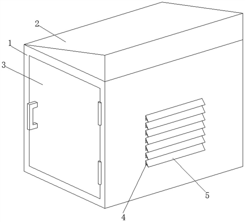
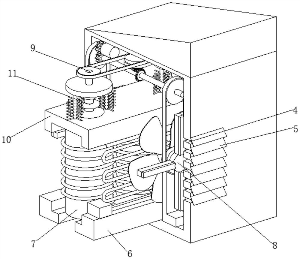
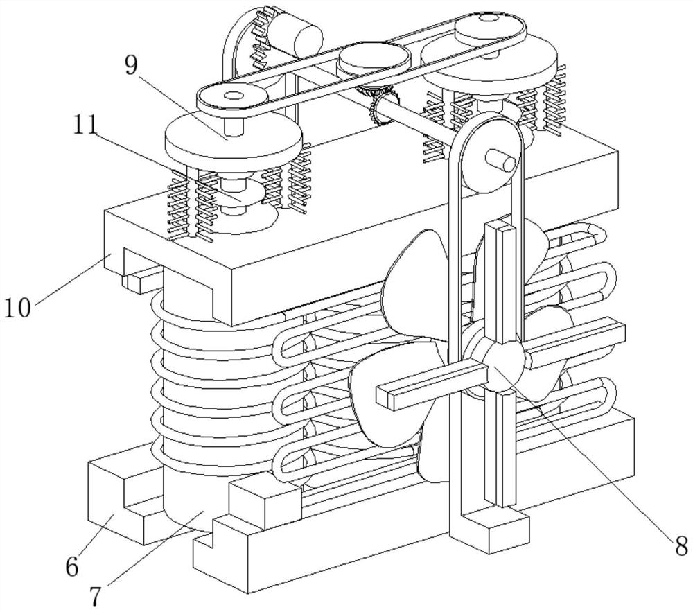
[0031] A transformer cooling device, such as Figure 1-Figure 6 As shown, it includes a box body 1, the top of the box body 1 is welded with an inclined block 2, the front part of the box body 1 is connected with a revolving door 3, and both sides of the box body 1 are provided with several air holes 4, and the box body 1 There are several baffles 5 welded on both sides of the box, and the baffles 5 are located above the air holes 4, the bottom wall inside the box 1 is connected with a base 6 by bolts, the upper surface of the base 6 is fixedly equipped with a coil 7, the box 1 The inner wall of the box body 1 is provided with a cooling mechanism 8, the top wall inside the box 1 is provided with a cleaning mechanism 9, the top of the coil 7 is fixedly installed with a top plate 10, and the top of the top plate 10 is clamped with a high-voltage bushing 11.

[0032] In this embodiment, there are two bases 6, and the two bases 6 are symmetrically distributed with the center line ...

Embodiment 2

[0041] Such as Figure 6-Figure 7 As shown, on the basis of Embodiment 1, in this embodiment, the axis of the turntable 861 and the axis of the first pulley 85 are welded and fixed, and the surface of the water-absorbing sponge 863 is in contact with the inner wall of the box body 1 .

[0042] The water-absorbing sponge 863 can absorb rainwater that cannot be blocked by the baffle plate 5, and prevent rainwater from entering the coil 7, thereby causing the transformer to break down and affecting the service life of the transformer.

[0043] The cleaning mechanism 9 includes a double-layer pulley 91, and the shaft center of the double-layer pulley 91 is welded with a No. 2 bevel gear 92 through a connecting rod. Transmission connection, the axis of the first pulley 93 and the second pulley 94 are welded with a runner 95 through a connecting rod, the bottom of the runner 95 is welded with two connecting rods 96, and the surface of the connecting rod 96 is inserted with several b...


PUM


Abstract

The invention relates to the technical field of transformers, and discloses a transformer cooling device which comprises a box body, an inclined block is welded to the top of the box body, a rotatingdoor is rotatably connected to the front portion of the box body, a plurality of air holes are formed in the two sides of the box body, and a plurality of baffles are welded to the two sides of the box body. A baffle is arranged in the box body and located above the air holes, a base is connected to the bottom wall of the interior of the box body through bolts, a coil is fixedly installed on the upper surface of the base, a cooling mechanism is arranged on the inner wall of the box body, a cleaning mechanism is arranged on the top wall of the interior of the box body, and a top plate is fixedly installed at the top end of the coil; a high-voltage sleeve is clamped to the top of the top plate, heat emitted by the coil can be absorbed and dissipated through a cooling mechanism, and thereforethe heat emitted by the coil can be reduced, and the situation that the service life of the transformer is affected due to the fact that an insulating material is damaged due to the fact that the temperature of a surrounding medium rises is prevented.

Description

technical field [0001] The invention relates to the technical field of transformers, in particular to a cooling device for transformers. Background technique [0002] A transformer is a static electrical device used to transform AC voltage and current to transmit AC power. It realizes power transfer based on the principle of electromagnetic induction. Transformers can be divided into power transformers, test transformers, instrument transformers and Transformers for special purposes: Power transformers are necessary equipment for power transmission and distribution, and power distribution for power users. [0003] At present, the transformer will emit heat during use. The heat generated by it will not only increase its own temperature, but also increase the temperature of the surrounding medium. When the winding temperature exceeds the heat resistance limit of the insulating material, the insulating material will be damaged. Damage, this is one of the main reasons why the t...

Claims


Application Information

Patent Timeline
Patent Type & Authority Applications(China)
IPC IPC(8): H01F27/08H01F27/10H01F27/40H01F27/28H01F27/02B08B1/00B08B1/04
CPCH01F27/2876H01F27/08H01F27/085H01F27/10H01F27/022H01F27/025H01F27/40B08B1/12B08B1/32
Inventor 不公告发明人
Owner 广州平红网络科技有限公司
Learn More