An agricultural straw treatment and reuse device

A straw and agricultural technology is applied in the field of agricultural straw treatment and reuse devices, which can solve the problems of increasing straw treatment steps, low straw treatment efficiency, and low straw treatment degree, and achieves reduction of treatment time, simple cutting process, and saving of pre-processing. The effect of processing time

Active Publication Date: 2021-11-02
湖南绿盟农业科技股份有限公司
View PDF15 Cites 0 Cited by
  • Summary
  • Abstract
  • Description
  • Claims
  • Application Information

AI Technical Summary

Problems solved by technology

However, before the straw treatment, the straw needs to be neatly arranged and fixed, which increases the working steps of the straw treatment. The efficiency of the straw treatment is low, and it needs to be cut several times to process the straw into the required size. The process of cutting the straw is cumbersome and difficult. In the process of straw cutting, the straw is reprocessed. It takes a long time for the cut straw to be used as fertilizer to corrode and provide nutrients for the soil. The degree of straw treatment is low, which is not convenient for the use of straw.

Method used


Image

  • An agricultural straw treatment and reuse device
  • An agricultural straw treatment and reuse device
  • An agricultural straw treatment and reuse device

Examples


Embodiment 1

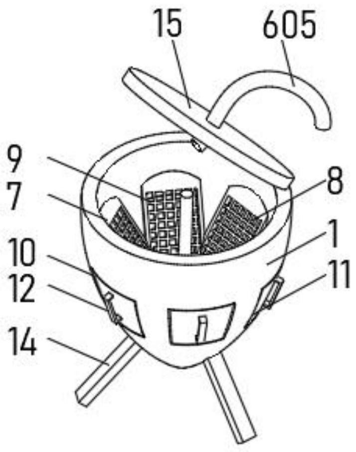
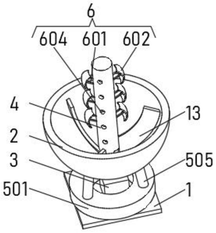
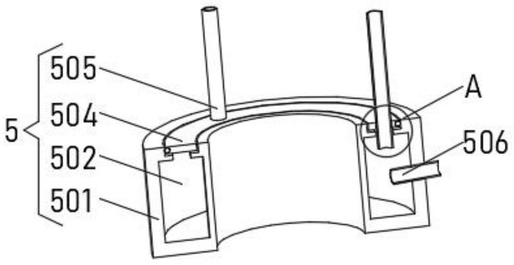
[0030] see Figure 1-5, the present invention provides a technical solution: an agricultural straw treatment and reuse device, comprising a housing 1, the housing 1 is a hollow spherical structure with an open top, the inner wall of the housing 1 is rotatably connected with an isolation chassis 2, and the inner bottom of the housing 1 is fixedly connected There is a rotating motor 3, and the output end of the rotating motor 3 is connected to a central rod 4, and the end of the central rod 4 away from the rotating motor 3 penetrates the isolation chassis 2 and extends to the top of the isolation chassis 2, and a lifting device 5 is installed on the inner bottom of the shell 1 One end of the top of the lifting device 5 runs through the isolation chassis 2, and the end of the central rod 4 located at the isolation chassis 2 is evenly equipped with a pusher device 6, and the inner wall of the shell 1 is evenly equipped with a cutting frame 7 above the isolation chassis 2. A longit...

Embodiment 2

[0037] see Figure 1-5 , the present invention provides a technical solution: on the basis of Embodiment 1, a pushing chamber 603 is provided inside the central rod 4, and a pushing port 604 is evenly opened on the outside of the central rod 4, and the pushing port 604 is connected with the pushing chamber 603 communicates, the top of the central rod 4 communicates with a delivery pipe 605 , the delivery pipe 605 runs through the central rod 4 and is rotationally connected with the central rod 4 .

[0038] The inner diameter of the pushing port 604 gradually decreases toward the direction away from the pushing chamber 603, and the end of the pushing port 604 away from the pushing chamber 603 is fixedly connected with an isolation net 606, and the outer side of the central rod 4 is fixedly connected with a protective net above the isolation net 606. The plate 607, the protective plate 607 is arranged obliquely downward.

[0039] When in use, water is delivered from the deliver...

Embodiment 3

[0041] see Figure 1-5 , the present invention provides a technical solution: on the basis of Embodiment 1, an upper rotary knife 13 is evenly installed on the inner bottom of the isolation chassis 2, and the upper rotary knife 13 is the same as the inner radian of the isolation chassis 2, and the upper rotary knife 13 is directed to Set on one side with a slant.

[0042] When in use, the rotating motor 3 starts to drive the central rod 4 and the isolation chassis 2 to rotate at the same time, and the inclined upper rotary knife 13 on the top of the isolation chassis 2 swings the straw on the isolation chassis 2 obliquely upward during the rotation of the isolation chassis 2 , the straw is sent to the top to collide with the pusher plate 602 and the cutting knife for cutting, which can assist in lifting the straw upwards to ensure that the straw can be lifted and cut, and avoid too much straw in the casing and the jet pipe 505 cannot be pushed upward, causing the straw to accu...


PUM


Abstract

The invention discloses an agricultural straw treatment and reuse device, which relates to the technical field of agricultural equipment, and comprises a casing, the casing is a hollow spherical structure with an open top, the inner wall of the casing is rotatably connected with an isolation chassis, and the inner bottom of the casing is A rotating motor is fixedly connected, and the output end of the rotating motor is connected to a central rod, and the end of the central rod away from the rotating motor penetrates the isolation chassis and extends above the isolation chassis. The agricultural straw treatment and reuse device can reduce the processing time before straw cutting, can cut the straw without tidying up the straw, saves the time of straw cutting pretreatment, the cutting process is simple, and the cutting efficiency is high. In the process of straw cutting, the straw is treated twice to reduce the time for straw corrosion to provide nutrients for the soil, improve the utilization speed of straw processing waste, and facilitate the use of straw processing waste.

Description

technical field [0001] The invention relates to the technical field of agricultural equipment, in particular to an agricultural straw treatment and reuse device. Background technique [0002] Straw is the general term for the stems, leaves and spikes of mature crops. It is a multi-purpose renewable biological resource. It is very necessary to realize the recycling of straw. [0003] Chinese invention CN107182461A discloses a straw cutting device, which includes a base. The right and left ends of the base are respectively fixedly equipped with a working backing plate and a lower rod. The upper end of the lower rod is connected to the upper rod through a bearing. Indexing rod, the right side of No. 1 indexing rod is hinged with No. 2 indexing rod, and the lower end of No. 2 indexing rod is hinged with movable frame, and there is a fixed device connecting the two between the movable frame and the upper rod. The lower part of the movable frame A seat frame is welded, and a No. ...

Claims


Application Information

Patent Timeline
Patent Type & Authority Patents(China)
IPC IPC(8): A01F29/02C05F11/00C05F17/90C05F17/964
CPCA01F29/025C05F11/00C05F17/90C05F17/964Y02W30/40
Inventor 王波
Owner 湖南绿盟农业科技股份有限公司
Why Eureka
Try Eureka