Lifting mechanism of vehicle charging device

A technology of charging device and lifting mechanism, which is applied in the direction of electric vehicle charging technology, charging station, lifting frame, etc., can solve the problems of complex driving structure of the lifting mechanism, and achieve the effect of compact structure, improved reliability and simple structure

Active Publication Date: 2021-03-23
XJ ELECTRIC +2
View PDF8 Cites 2 Cited by
  • Summary
  • Abstract
  • Description
  • Claims
  • Application Information

AI Technical Summary

Problems solved by technology

[0005] The purpose of the present invention is to provide a lifting mechanism of a vehicle charging device to solve the problem that the driving structure of the lifting mechanism is relatively complicated in the prior art

Method used


Image

  • Lifting mechanism of vehicle charging device
  • Lifting mechanism of vehicle charging device
  • Lifting mechanism of vehicle charging device

Examples


Embodiment Construction

[0033] The present invention will be further described below in conjunction with accompanying drawing.

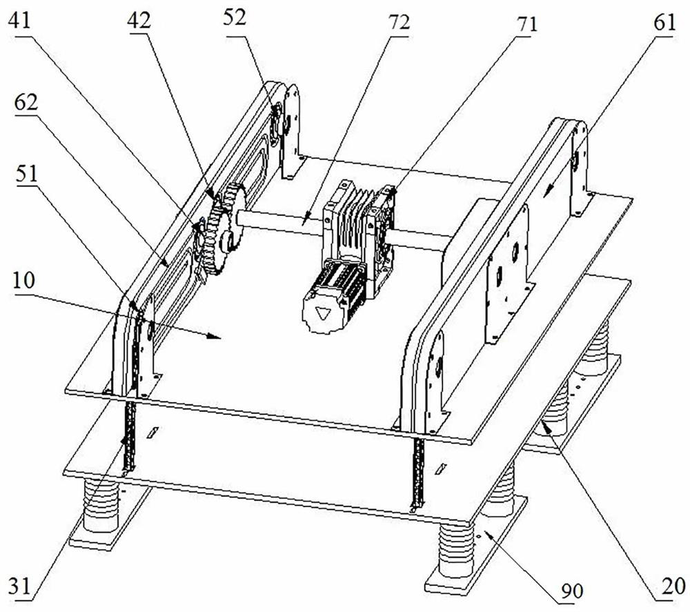
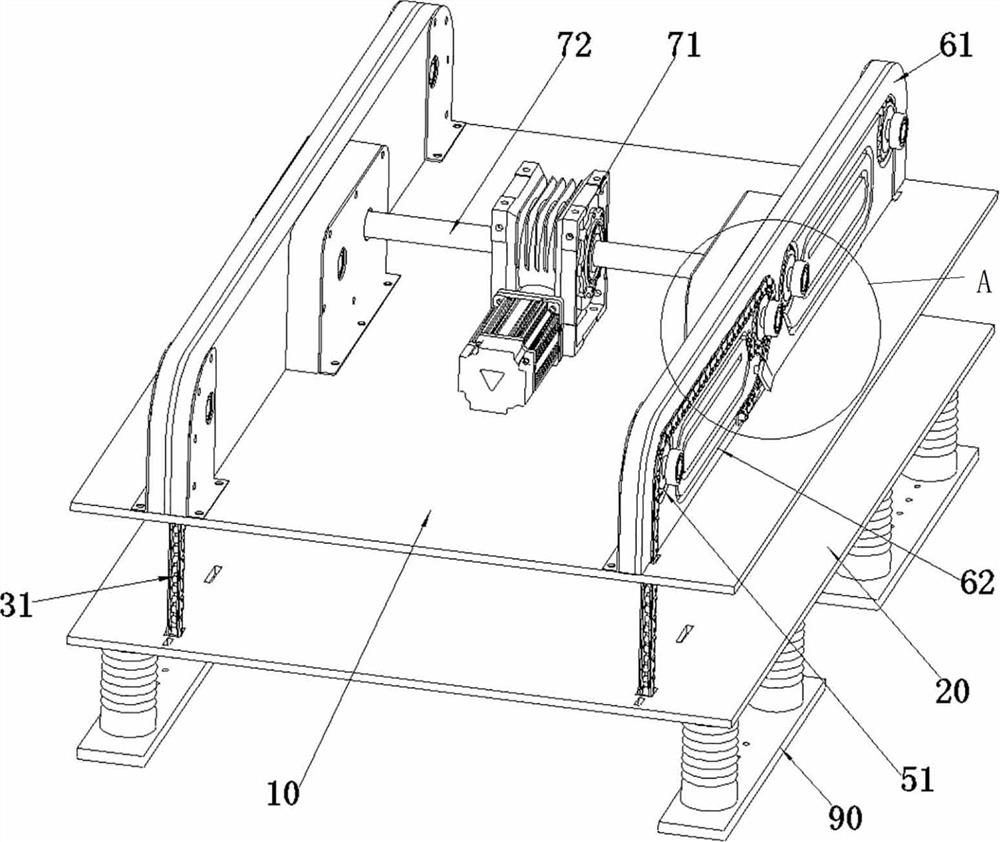
[0034] An example of the lifting mechanism of the vehicle charging device of the present invention is Figure 1 to Figure 6 As shown, it includes a fixed base 10 and a liftable electrode base 20 arranged below the fixed base 10. The fixed base 10 is used to be fixed to objects such as the frame body and the ceiling of the charging station as a mounting base for the lifting mechanism; the lifting motor base is used To assemble the charging electrode 90 to realize the charging of the vehicle. The liftable fixing seat 10 can be hoisted on the fixing seat 10 liftably by the anti-bending chain, and the anti-bending chain includes a left side anti-bending chain 31 and a right side anti-bending chain 32, and the lower end of the anti-bending chain passes through the fixing seat 10 and is connected to the Can be lifted on the motor base.

[0035] Take the direction perpendicular ...


PUM


Abstract

The invention relates to a lifting mechanism of a vehicle charging device. The lifting mechanism of the vehicle charging device comprises a fixed base and a lifting electrode base. The lifting electrode base is hoisted on the fixed base in a lifting manner through a left side anti-bending chain and a right side anti-bending chain, and driving chain wheels and reversing chain wheels are arranged onthe fixed base; the driving chain wheels comprise the left driving chain wheel and the right driving chain wheel which are used for driving a left anti-bending chain and a right anti-bending chain correspondingly; the reversing chain wheels comprise the left reversing chain wheel and the right reversing chain wheel, and the left anti-bending chain and the right anti-bending chain are wound aroundthe left reversing chain wheel and the right reversing chain wheel correspondingly to achieve downward reversing; and the left driving chain wheel and the right driving chain wheel are arranged in the middle of the fixed base in the left-right direction and coaxially connected with a left driving gear and a right driving gear correspondingly, the left driving gear and the right driving gear are engaged with each other and have the same tooth number, and one of the left driving gear and the right driving gear is connected with a driving motor. According to the above scheme, the problem that inthe prior art, a driving structure of a lifting mechanism is complex is solved.

Description

technical field [0001] The invention relates to a lifting mechanism of a vehicle charging device. Background technique [0002] With the development of society, people pay more and more attention to the problem of environmental pollution, more and more electric vehicles are used, users' demand for long driving range is getting higher and higher, the battery capacity of electric vehicles continues to increase, and high-power commercial The demand for cars is constantly increasing. In the prior art, high-power commercial vehicles generally use top charging, and their lifting mechanism generally adopts a scissor lifting mechanism, which has a complex structure, large volume, and heavy weight. [0003] The Chinese patent with the authorized announcement number CN207842691U and the authorized announcement date of 2018.09.11 discloses a sinking charging mechanism for a group control charging system. The charging mechanism includes a fixed seat fixed on the top of the charging sta...

Claims


Application Information

Patent Timeline
IPC IPC(8): B66F7/02B66F7/28B60L53/14
CPCB66F7/02B66F7/28B60L53/14Y02T10/70Y02T10/7072Y02T90/14
Inventor 李承光敬兵穆贝贝魏伟方春阳杜永平李明明殷帅兵郭胜军李晓虎
Owner XJ ELECTRIC
Why Eureka
Try Eureka