

High-voltage switch cabinet with moisture-proof and dust-proof functions
A high-voltage switchgear and functional technology, applied in the field of high-voltage switchgear, can solve the problems of reducing the service life of the switchgear, not having moisture-proof and dust-proof functions, and affecting the normal use of the switchgear, achieving reduced heat dissipation, strong practicability, and reasonable structure Effect
- Summary
- Abstract
- Description
- Claims
- Application Information
AI Technical Summary
Problems solved by technology
Method used
Image

Examples
Embodiment 1
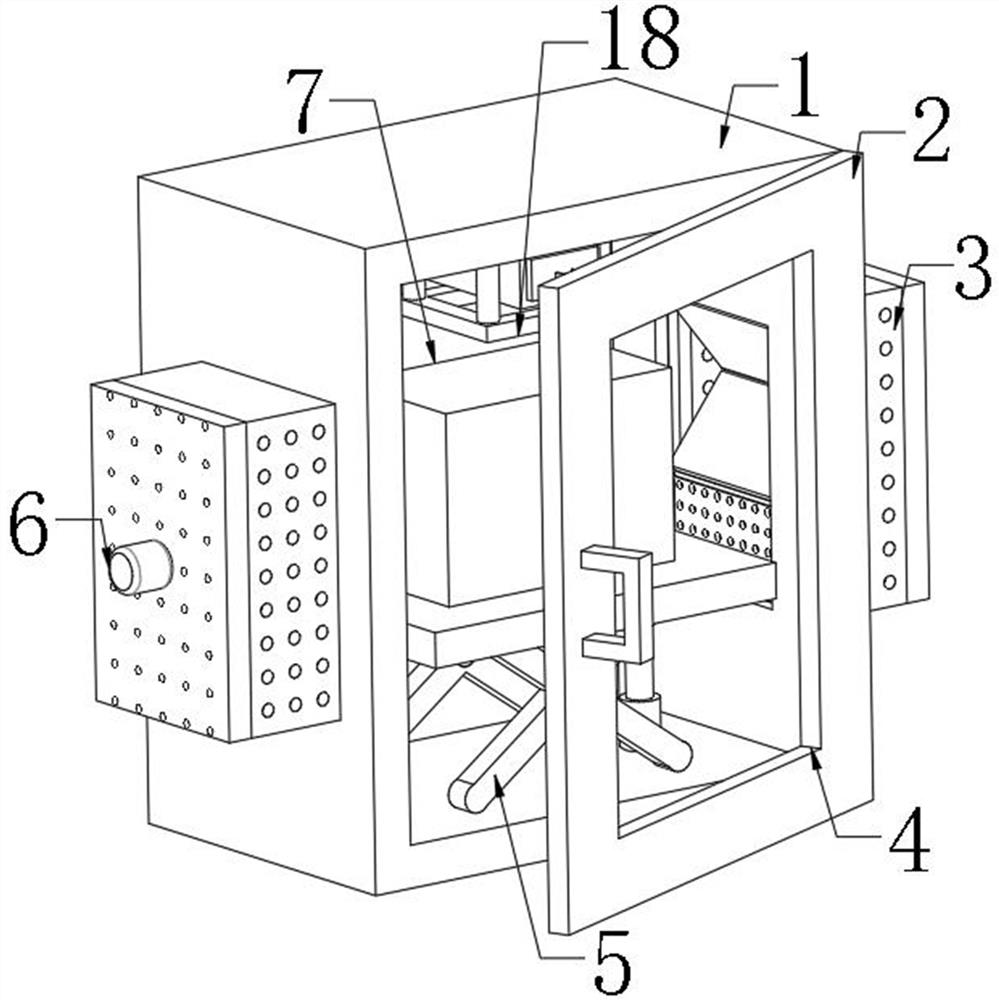
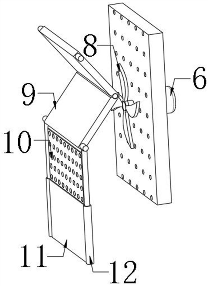
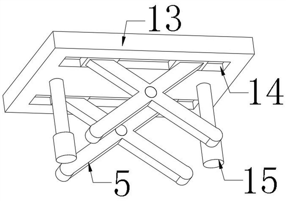
[0027] refer to Figure 1-3 , a high-voltage switch cabinet with moisture-proof and dust-proof functions, including a cabinet body 1 and a lifting plate 13, the outer walls of both sides of the cabinet body 1 are provided with installation holes, the inner walls of the installation holes are provided with sliding grooves, and the inner walls of the sliding grooves are passed through bolts The sliding rail 17 is fixed, and the inner wall of the sliding rail 17 is slidably connected with two baffles 9, and the two baffles 9 are connected by hinges, and the bottom inner wall of the installation hole is provided with an installation groove, and both sides of the inner wall at the bottom of the installation groove are fixed by bolts There is a first electric telescopic rod 12, one end of the piston rod of the first electric telescopic rod 12 is fixed on the bottom outer wall of the baffle plate 9 by bolts, and the outer walls on both sides of the cabinet body 1 are fixed with a dust...
Embodiment 2
[0036] refer to Figure 4, a high-voltage switch cabinet with moisture-proof and dust-proof functions, the cabinet body 1 and the lifting plate 13, the outer walls of both sides of the cabinet body 1 are provided with mounting holes, the inner walls of the mounting holes are provided with sliding grooves, and the inner walls of the sliding grooves are fixed by bolts Sliding rail 17 is arranged, and the inner wall of sliding rail 17 is slidably connected with two baffle plates 9, and two baffle plates 9 are connected by hinges, and the bottom inner wall of the mounting hole has a mounting groove, and both sides of the mounting groove bottom inner wall are fixed by bolts. The first electric telescopic rod 12, one end of the first electric telescopic rod 12 piston rods is fixed on the bottom outer wall of the baffle plate 9 by bolts, and the both sides outer walls of the cabinet body 1 are all fixed with a dustproof box 3 by bolts, and the dustproof box 3 One side outer wall is f...
PUM
 Abstract
Description
Claims
Application Information