Millimeter wave beam alignment method based on sparse coding

A sparse coding, millimeter-wave technology, applied in space transmit diversity, radio transmission systems, electrical components, etc., can solve problems such as difficulty in obtaining millimeter-wave channel information, reduced gain, long scan time, etc.

Active Publication Date: 2021-03-23
UNIV OF ELECTRONICS SCI & TECH OF CHINA
View PDF5 Cites 3 Cited by
  • Summary
  • Abstract
  • Description
  • Claims
  • Application Information

AI Technical Summary

Problems solved by technology

[0003] However, as the number of antennas increases, it will be more difficult to obtain millimeter-wave channel information. Therefore, a large number of recent literatures use the sparsity of millimeter-wave channels and combine compressed sensing technology (CS) to estimate Massive MIMO channels.
However, these related technologies all increase the computational complexity in the operation of the algorithm due to the large matrix inversion operation in the calculation process
In order to reduce the computational complexity and reduce the difficulty of hardware implementation, the existing protocols mostly utilize the narrow nature of millimeter wave beams to implement beam scanning or layered scanning. However, the disadvantage of these algorithms is that they either require a longer Scan time either requires setting up a proper feedback link or reducing the gain for the first beam scan

Method used


Image

  • Millimeter wave beam alignment method based on sparse coding
  • Millimeter wave beam alignment method based on sparse coding
  • Millimeter wave beam alignment method based on sparse coding

Examples


Embodiment

[0061] This example includes the following steps:

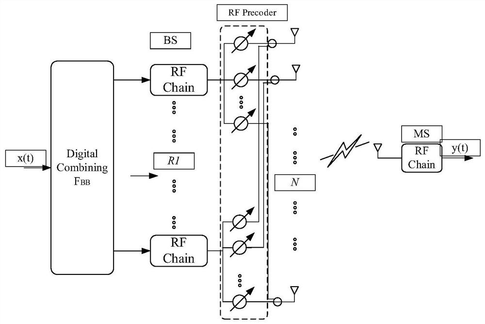
[0062] S1: In the first stage, the BS sends T pilot signals to estimate the time-varying channel, and at the same time, the BS uses a multi-beam receiving matrix to receive. Specifically, at time t, the BS sends the pilot vector Receiver uses Received, both vectors satisfy the following conditions

[0063] f(t)=F RF (t)F BB (t)=F BS ψ(t)

[0064] w(t)=W RF (t)W BB (t)=F MS (t)v(t)

[0065] S2: Separately intercept the T pieces of data received by the i-th radio frequency link and process them separately as follows

[0066]

[0067] S3: Divide the measurement matrix ψ into two parts and design separately as follows

[0068] ψ=G⊙S

[0069] where ⊙ represents a row tensor operation, where G is a sparse pattern matrix, and S is a node identification matrix.

[0070] zero-ton: Define a check node as zero-ton when its multi-beam detection (the connecting line of the node on the right of the figure) does not reach ...


PUM


Abstract

The invention belongs to the technical field of millimeter wave communication, and particularly relates to a millimeter wave beam alignment method based on sparse coding. 1, a transmitting precoding matrix of a transmitting end and a receiving precoding matrix of a receiving end are reasonably designed, a plurality of wave beams are formed at the transmitting end and the receiving end at the sametime, and then independent link data are selected. In this way, a beam alignment problem is converted into a sparse coding and decoding problem. 2, the measurement matrix is divided into two parts, the two parts are respectively designed, namely a sparse graph design and an identification matrix design, and the minimum graph row number is defined through a theoretical lower limit table obtained byderivation; experimental results show that the proposed algorithm is simpler and easier to implement than a traditional method based on compressed sensing, and it can also be proved that the proposedmethod is superior to a traditional beam alignment method based on sparse coding and has robustness for different antenna numbers.

Description

technical field [0001] The invention belongs to the technical field of millimeter wave communication, in particular a method for aligning millimeter wave beams based on sparse coding. Background technique [0002] With the development of ultra-high-definition video transmission, intelligent vehicle communication and virtual reality technology in the future, the capacity of the global mobile communication system will usher in a huge demand. The future demand for data transmission rates may be 1000 times the capacity of existing systems. Millimeter wave communication technology is regarded as a key technology for future wireless networks to meet future high-speed requirements due to its ability to utilize larger communication bandwidths to generate greater transmission rates. For example, in the latest 802 / 11ay standard of IEEE, the 60GHz communication technology can already provide a transmission rate up to 20Gbps. However, communication in the mmWave frequency band has inh...

Claims


Application Information

Patent Timeline
Patent Type & Authority Applications(China)
IPC IPC(8): H04B7/0456H04B7/08
CPCH04B7/0456H04B7/086
Inventor 程龙王志强岳光荣肖培
Owner UNIV OF ELECTRONICS SCI & TECH OF CHINA
Why Eureka
Try Eureka